background image


Part Number: 875-0021-003


Date: May 2001


ABX-3 / MBX-3


Reference Manual


Summary of Contents for ABX-3

Page 1: ...Part Number 875 0021 003 Date May 2001 ABX 3 MBX 3 Reference Manual ...

Page 2: ... Reference Manual ii CSI Wireless Inc 1200 58 Avenue S E Calgary Alberta Canada T2H 2C9 Telephone number 1 403 259 3311 Fax number 1 403 259 8866 E mail address info csi wireless com Web Site www csi wireless com ...

Page 3: ...ssion from CSI Wireless Inc FCC Notice The ABX 3 and MBX 3 Beacon Receivers comply with the Part 15 Subpart J Emission Requirement for Class A digital devices for use in commercial business and industrial environments The ABX 3 and MBX 3 Beacon Receivers comply with relevant sections of the following European harmonized documents n EN 60945 Marine Navigation Requirements n EN 50081 1 Emissions for...

Page 4: ...ess for a particular purpose CSI Wireless hereby disclaims and excludes all other warranties In no event shall CSI Wireless be liable for direct indirect incidental collateral or consequential damages of any kind including but not limited to damages resulting from installation or use quality performance or accuracy of CSI Wireless products This warranty provides you with your exclusive remedies fo...

Page 5: ... person s or party s shall render this warranty null and void CSI Wireless does not warrant or guarantee the precision or accuracy of positions obtained when using CSI Wireless products Product accuracy as stated in CSI Wireless literature and or product specifications serves to provide only an estimate of achievable accuracy based on n Specifications provided by the US Department of Defense US Do...

Page 6: ...ABX 3 MBX 3 Reference Manual vi ...

Page 7: ... Cautions and Warnings xix 1 Introduction 1 1 1 GPS 1 1 1 1 How it Works 1 1 1 2 GPS Services 2 1 2 Differential GPS 2 1 2 1 How it Works 2 1 2 2 Real Time DGPS 3 1 3 DGPS Format 3 1 4 Radiobeacon DGPS Service 4 1 4 1 Radiobeacon Range 4 1 4 2 Radiobeacon Reception 5 1 4 3 Radiobeacon DGPS 5 1 4 4 Radiobeacon Coverage 6 1 5 Factors Affecting Positioning Accuracy 7 1 6 Beacon Receiver Information 9...

Page 8: ...ing the Receiver 16 2 3 1 Receiver Placement 16 2 3 2 Environmental Considerations 17 2 3 3 Power Considerations 17 2 3 4 Grounding the Receiver 18 2 3 5 Connecting the Receiver To External Devices 19 2 3 6 RS 232C and RS 422 Operation 21 2 4 Installing the Antenna 23 2 4 1 Antenna Placement To Optimize Reception 23 2 4 2 MBA 3 E Field Antenna 24 2 4 3 MBL 3 H Field Antenna 26 2 4 4 ABL 1 Aircraft...

Page 9: ... 4 1 1 Lock Status 37 4 2 Factory Default Settings 37 4 3 Tune Modes 38 4 3 1 Automatic Beacon Search ABS Mode 38 4 3 2 Manual Mode 39 4 4 MBX 3 Display Modes 40 4 4 1 MBX 3 Mode 40 4 4 2 MBX E Mode 40 4 5 MBX 3 Menu System 41 4 5 1 Start Up Sequence 42 4 5 2 Beacon Status 42 4 5 3 Setup 45 4 5 4 Position Status MBX E Mode Only 48 4 5 5 Satellites MBX E Mode Only 50 4 5 6 Menu System Shortcuts 51 ...

Page 10: ... 5 2 Description of NMEA 0183 56 5 3 NMEA Message Elements 57 5 3 1 CSI Wireless DGPS Command Center 57 5 4 ABX 3 Supported Messages 58 5 5 MBX 3 Supported Messages 59 5 6 Response Message 60 5 7 NMEA 0183 Commands 60 5 7 1 Standard Commands 60 5 7 2 Proprietary Commands 63 5 8 NMEA 0183 Queries 67 5 8 1 Standard Queries 67 5 8 2 Proprietary Queries 68 5 9 Firmware Updates 72 6 Troubleshooting 74 ...

Page 11: ...ABX 3 MBX 3 Reference Manual xi ...

Page 12: ...422 21 Figure 2 4 RS 232 RS 422 Configuration 22 Figure 2 5 Beacon Receiver MBA 3 Grounding Requirement 25 Figure 2 6 ABX 3 MBX 3 Internal Signal Splitter Option 30 Figure 3 1 ABX 3 LED Indicators 31 Figure 4 1 MBX 3 Display and Keypad 36 Figure 4 2 MBX 3 Lock Indicator 37 Figure 4 3 MBX E Position Fix Indicator 41 Figure 4 4 MBX 3 Menu System 44 Figure A 1 External Signal Splitter 85 ...

Page 13: ...ABX 3 MBX 3 Reference Manual xiii ...

Page 14: ...n Health Status Values 44 Table 4 4 Receiver Performance SNR Reading 52 Table 5 1 NMEA Message Elements 57 Table 5 2 ABX 3 Supported NMEA Messages 58 Table 5 3 MBX 3 Supported NMEA Messages 59 Table 5 4 ABX 3 Baud Rates 64 Table 5 5 MBX 3 Baud Rates 65 Table 5 6 MBX 3 Factory Pre Configured Baud Rates 65 Table 5 7 MBX 3 Display Modes 66 Table 6 1 ABX 3 Troubleshooting 74 Table 6 2 MBX 3 Troublesho...

Page 15: ...ABX 3 MBX 3 Reference Manual xv Table A 6 ABL 1 Aircraft Antenna Specifications 83 Table A 7 Antenna Signal Splitter Specifications 84 ...

Page 16: ...ift keying MSK demodulator that incorporates dual channel digital technology The ABX 3 and MBX 3 obtain differential GPS corrections broadcast from radiobeacons adhering to the standards defined by the International Association of Lighthouse Authorities IALA and operate in the frequency range of 283 5 to 325 kHz Both receivers feature a proven fully automatic radiobeacon search algorithm The MBX 3...

Page 17: ... Specifications details the technical characteristics of the ABX 3 and MBX 3 receivers antennas and accessories Appendix B Beacon Information discusses the CSI Wireless maintained World Beacon listing and how to obtain this document on the Internet The Further Reading section provides a listing of GPS DGPS sources for further information The Index provides a listing of the locations of subject mat...

Page 18: ...ion RMA number before returning any product to CSI Wireless If you are returning a product for repair you must also provide a fault description before CSI Wireless will issue an RMA number A proof of purchase is required for warranty purposes When providing the RMA number CSI Wireless will provide you with shipping instructions to assist you in returning the equipment World Wide Web Site CSI Wirel...

Page 19: ...ndicates that you should press the down arrow button of the MBX 3 receiver keypad Notes Cautions and Warnings Notes Cautions and Warnings stress important information regarding the installation configuration and operation of the ABX 3 and MBX 3 Beacon Receivers Note Notes outline important information of a general nature Caution Cautions inform of possible sources of difficulty or situations that ...

Page 20: ......

Page 21: ... 1 How it Works These satellites transmit coded information to GPS users at UHF 1 575 GHz frequencies that allows user equipment to calculate a range to each satellite GPS is essentially a timing system ranges are calculated by timing how long it takes for the GPS signal to reach the user s GPS antenna To calculate a geographic position the GPS receiver uses a complex algorithm incorporating satel...

Page 22: ...vigation applications an accuracy of 100 meters is insufficient and differential positioning techniques must be employed 1 2 Differential GPS The purpose of differential GPS DGPS is to remove the effects of SA atmospheric errors timing errors and satellite orbit errors while enhancing system integrity 1 2 1 How it Works DGPS involves setting up a reference GPS receiver at a point of known coordina...

Page 23: ... 3 DGPS Format For manufacturers of GPS equipment commonality is essential to maximize the utility and compatibility of a product The governing standard associated with GPS is the Interface Control Document ICD GPS 200 maintained by the US DoD This document provides the message and signal structure information required to access GPS Like GPS DGPS data and broadcast standards exist to ensure compat...

Page 24: ... of the surface over which it travels A signal will propagate further over a surface with high conductivity than over a surface with low conductivity Lower conductivity surfaces such as dry infertile soil absorb the power of the transmission more than higher conductivity surfaces such as seawater or arable land A radiobeacon transmission has three components a direct line of sight wave a ground wa...

Page 25: ...eacon reception and include n Engine noise n Alternator noise n Noise from Power lines n DC to AC inverting equipment n Electric devices such as CRT s electric motors and solenoids Noise generated by this type of equipment can mask the beacon signal reducing or impairing reception Section 2 4 1 presents an effective procedure to minimize impact of local noise on beacon reception when using this co...

Page 26: ...ransmit n The Type 7 message contains the radiobeacon almanac information composed of location frequency service range and health information of sister stations for the currently tuned beacon n The Type 16 message provides users with a 90 character text string that may contain information regarding the status of the system weather warnings etc Radiobeacon DGPS is often referred to as a local area ...

Page 27: ... n Age of the received differential corrections n Atmospheric conditions at the beacon and remote user locations n Satellite geometry often expressed as a Dilution of Precision DOP n Magnitude of multipath present at the remote station n Quality of the GPS receiver being used at both the reference and remote stations The distance between a remote user and the reference station is often considerabl...

Page 28: ...eceiver n Any data loss that occurs through reception problems Most of these delays require less than a second though in some instances depending upon the amount of information being transferred overall delays of three to five seconds may occur Latency can become a concern if lock on the differential signal is lost for ten seconds or more To account for latency and the rapidly changing SA error a ...

Page 29: ...longer route to the GPS antenna Certain precautions will minimize GPS antenna sensitivity to these reflected signals Operating away from large reflective structures such as buildings or using special antennas and GPS equipment can help to reduce the impact of multipath For most consumer level applications a small amount of multipath is tolerable The quality of a GPS receiver has a dramatic influen...

Page 30: ...ility with differential ready GPS products In addition the MBX 3 features a 2 line by 16 character display and 3 key control panel for operation of the receiver and monitoring performance It also has the ability to display position and satellite information from a connected GPS receiver s NMEA data output messages The ABX 3 receiver is a cost effective black box product with power and lock LED ind...

Page 31: ...static P static and other forms of predominate E field noise than a Whip antenna The H field antenna receives broadcast signals which it band pass filters before amplifying the signal and passing it to the beacon receiver The MBL 3 antenna housing is a rugged weather tight PVC plastic enclosure with a 1 14 UNS threaded base A magnetic mount is available to install this antenna on ferrous and non f...

Page 32: ...beacon receiver As with the MBA 3 the MGW 1 requires an antenna ground connection This antenna may be used with CSI Wireless s GBX combined beacon GPS receiver series or with separate beacon and GPS receivers The latter configuration requires the MBX 3 internal signal splitter option or the external antenna signal splitter described in the following section As with the MBL 3 this antenna is availa...

Page 33: ...or connection between the external splitter the beacon receiver and the GPS receiver CSI Wireless also offers an Internal Signal Splitter on ABX 3S and MBX 3S receiver models to reduce the complexity of cable connections Refer to Section 2 5 for more information on this option ...

Page 34: ...ABX 3 MBX 3 Reference Manual 14 ...

Page 35: ...n Power Cable n Antenna Cable n Data Cable n Universal Mounting Bracket n Reference Manual 2 2 Receiver Layout and Connections The ABX 3 and MBX 3 receivers are easily installed requiring only power data antenna and ground connections Both receivers have identical real panel connections Figure 1 1 illustrates the required receiver cable connections Caution The ABX 3 and MBX 3 receivers provide 10 ...

Page 36: ...eceiver performance and ease of operation you should consider the information presented in the following sections when installing the ABX 3 or MBX 3 receiver 2 3 1 Receiver Placement The Universal Mounting Bracket U bracket supplied with the system is used to secure the receiver to the selected mounting surface You may ...

Page 37: ...er status Use the Universal Mounting Bracket U bracket as a template when planning and drilling through holes 2 3 2 Environmental Considerations Both the ABX 3 and MBX 3 are designed to operate within enclosed environments where the temperature remains between 30 C and 70 C and relative humidity is less than 95 They may be stored between 40 C and 80 C 2 3 3 Power Considerations The ABX 3 and MBX 3...

Page 38: ...f the power cable protects the receiver from power surges The fuse container should remain accessible after installation Caution Do not operate either the ABX 3 or MBX 3 with the 1 5 A fuse bypassed Such modification will void the product warranty 2 3 4 Grounding the Receiver For best performance connect the ground screw labelled GND on the back of the ABX 3 and MBX 3 to a counterpoise ground This...

Page 39: ...ver at the RS 232C interface level Table 2 3 provides the pin assignments for the data port at the RS 422 level The wire colors listed in Tables 2 2 and 2 3 are specific to a custom DB 9P to un terminated data cable CSI Wireless PN 051 0005 000 Contact CSI Wireless if you wish to purchase this cable Table 2 2 Receiver Data Pin out RS 232C Interface Level Pin Color P N 051 0005 000 Signal Descripti...

Page 40: ...g device transmit line This is required for display of GPS information on the MBX 3 LCD display when in MBX E mode and for tuning of the ABX 3 and MBX 3 receivers remotely You must connect the signal ground pin 5 of the beacon receiver to the signal ground of the external GPS device Figure 2 2 illustrates this requirement for a GPS receiver operating at the RS 232C communications level ABX 3 MBX 3...

Page 41: ...ds 2 3 6 RS 232C and RS 422 Operation A majority of GPS receiver products communicates at the RS 232C level similar to a PC computer However there are a number of chart plotting devices incorporating GPS capabilities that operating at the RS 422 interface level The default communication level of the ABX 3 and MBX 3 is RS 232C To switch from the default RS 232C communication level you must remove t...

Page 42: ...not draw the printed circuit board fully out of the enclosure Instead slide the board out no more than two inches before reaching in to reposition the RS 232C RS 422 slide switch Use of a plastic ball point pen is recommended when making this adjustment Figure 2 4 illustrates the location of the RS 232C RS 422 slide switch within the receiver RS 232 RS 422 S1 Figure 2 4 RS 232 RS 422 Configuration...

Page 43: ...ated by your vehicle vessel or surroundings may affect your beacon system performance To minimize this impact you should locate the antenna outside the path of a radar beam away from any transmitting antennas and away from any other source of interference such as motors solenoids and other electronics Your receiver calculates a Signal to Noise Ratio SNR measured in dB Decibels which indicates the ...

Page 44: ...o be mounted on the highest point on the vessel or vehicle Degraded performance resulting from precipitation static will be most significant if the antenna is at the highest point If access to a vessel mast is limited you may rail mount the antenna using appropriate mounting hardware The following list provides instructions to install the MBA 3 on a marine pole mount n Install the pole mount in th...

Page 45: ...A 3 is also available with a 10 meter antenna pigtail called the MBA 3A The pigtail of this version is terminated with a BNC P connector for direct connection to the beacon receiver The connector is removable to aid in routing the cable through a bulkhead with a minimal opening As the connector is removable do not cut the connector off in order to run the cable You should minimize the number of ti...

Page 46: ... ground connection is required with the MBL 3 Note Mount this antenna 8 cm 3 inches above any metal surface upon which it is installed Caution Antennas threaded onto a mount should be tightened only by hand Do not use tools to install the MBL 3 as this may cause damage to the antenna Damage caused by over tightening is not covered under warranty 2 4 4 ABL 1 Aircraft Antenna The ABL 1 is installed ...

Page 47: ...ructed view of the sky and 8 cm 3 inches away from any metal surface Caution Antennas threaded onto a mount should be tightened only by hand Do not use tools to install the MGL 3 as this may cause damage to the antenna Damage caused by over tightening is not covered under warranty 2 4 6 Routing and Securing the Antenna Cable CSI Wireless beacon antennas require a 50 Ω impedance antenna extension c...

Page 48: ... antenna to the beacon receiver before you apply power to the receiver Warning Improperly installed cables near machinery can be dangerous 2 4 7 Optional Antenna Mounts CSI Wireless offers a number of antenna mounting accessories as described in the following subsections 2 4 7 1 Magnetic Mount The magnetic mount can be used to install the MBL 3 or MGL 3 antennas on any ferrous surface such as the ...

Page 49: ...ey Adapter The Survey Adapter is a threaded insert available for use with the MBL 3 and the MGL 3 antennas It converts the standard 1 14 UNS 2B thread to a 5 8th inch thread frequently used with survey equipment CSI Wireless PN 600 0005 006 2 5 Internal Signal Splitter Optional The ABX 3S and MBX 3S receivers include an optional internal signal splitter for use with the MGL 3 antenna The Internal ...

Page 50: ...ABX 3 MBX 3 Reference Manual 30 MGL 3 ANT GPS DATA PWR GND ANT DATA OUT PWR GND ABX 3S MBX 3S GPS Receiver RTCM IN Figure 2 6 ABX 3 MBX 3 Internal Signal Splitter Option ...

Page 51: ...u system present on the MBX 3 receiver Refer to Chapter 5 for instructions on how to program the ABX 3 through serial data connection and NMEA 0183 formatted messages 3 1 LED Indicators The ABX 3 features a red and green LED on the front panel to indicate receiver power and lock status respectively When the red LED labeled PWR illuminates the ABX 3 is receiving 9 40 VDC from the external power sou...

Page 52: ...y Stop Bit Interface Level 4800 8 None 1 RS 232C 3 3 Tune Modes The ABX 3 may be operated in either Automatic or Manual Tune Mode In Automatic Beacon Search ABS Mode the receiver identifies and tunes to the station providing the strongest DGPS signal In Manual Mode you specify the frequency to which the receiver will tune Refer to Section 5 7 1 to switch between Automatic and Manual Tune modes usi...

Page 53: ...oor to determine the station providing the strongest RTCM signal The receiver s primary channel locks to the first identified DGPS broadcast while the second channel continues searching in the background for superior beacon signals If no signal is available the ABX 3 will initiate a fresh Global Search continuing this cycle until it finds a valid beacon 3 3 1 2 Background Search During the Backgro...

Page 54: ...ration are discussed in Sections 5 7 1 1 and 5 7 1 2 respectively 3 4 ABX 3 Receiver Performance SNR Reading The Signal to Noise Ratio SNR best describes beacon receiver performance The SNR is the height of the signal above the noise floor The higher the SNR the better the ABX 3 is receiving the signal Although you may monitor the SNR by interfacing to a PC computer running a terminal program you ...

Page 55: ... PSLIB NMEA sentence When interfacing a Garmin GPS receiver with the ABX 3 set the input output protocols to RTCM NMEA and change the baud rate of the Garmin to 4800 You may manually tune the ABX 3 by selecting the desired frequency from the menu system of a Garmin GPS product When tuning manually the ABX 3 will remain tuned the last frequency even after subsequent power up To return the ABX 3 to ...

Page 56: ...erial data connection and NMEA 0183 messages 4 1 Front Display and Keypad The MBX 3 features a 2 line by 16 character LCD and 3 key control panel The control panel is composed of an up arrow enter and down arrow key These keys allow you to navigate through the intuitive MBX 3 menu system configuring operating parameters and viewing status information Figure 4 1 shows the display and keypad of the ...

Page 57: ...to an RTCM signal and open when no broadcast is available for the specified frequency and or MSK bit rate No Lock Lock Figure 4 2 MBX 3 Beacon Lock Indicator 4 2 Factory Default Settings Table 4 1 presents the factory default MBX 3 operation settings while Table 4 2 lists the default communication settings These operation and port settings are valid upon initial power up The MBX 3 maintains any ch...

Page 58: ...ncy to which the receiver will tune Refer to Figure 4 4 and Section 4 8 to switch between Automatic and Manual Tune modes using the display and keypad 4 3 1 Automatic Beacon Search ABS Mode The MBX 3 receiver operates in Automatic Beacon Search ABS mode by default selecting and tuning to the most appropriate beacon without operator intervention The MBX 3 uses its two independent channels to identi...

Page 59: ...h Global Search continuing this cycle until it finds a valid beacon 4 3 1 2 Background Search During the Background Search the second channel examines all frequencies at both the 100 and 200 bps MSK bit rates to identify beacons possessing superior signal quality If a DGPS broadcast is identified that exhibits a 2 dB greater signal strength than that of the primary station the receiver will automa...

Page 60: ...r operation and configuration The receiver outputs RTCM data through the transmit data line of the serial port and receives configuration commands and status queries through the data port receive pin 4 4 2 MBX E Mode In MBX E or external GPS input mode standard NMEA 0183 GPS messages GPGGA GPVTG GPZDA and GPGSV are input from an external GPS receiver and the position navigation and satellite infor...

Page 61: ...scribes the three states of GPS lock No Fix GPS DGPS Figure 4 3 MBX E Position Fix Indicator In the first state the two parallel vertical lines indicate that no position fix is available The second state denoted by the hollow circle between the two parallel vertical lines states that the receiver is tracking four satellites or more and is computing a position This indicator is a symbol representin...

Page 62: ... serial number software version and the current display mode Following initialization the receiver proceeds directly to the Beacon Status branch of the menu tree When operating in MBX E mode the MBX 3 will proceed directly to the Position Status branch of the menu tree 4 5 2 Beacon Status The Beacon Status section of the menu tree provides access to information related to the status of the receive...

Page 63: ...305 0 B200 SS 000 SNR 000 PRF 100 Q25 Unselected Bx ID 00000 H 0 Baud Rt 4800 XBX3 Mode Hgt Unit Meters User Continent Country Beacon Name Select User Edit User Erase User User Entry User Entry Lat Lon Hgt Hdg UTC Age Back Back Back Back Back Back HDOP Ch12 SV00 El00 Az 000 SNR 00 MBX E Mode MBX 3 Mode Enter Key Down Arrow Up Arrow Short Cut User Entry Legend SV Count Vel Unit KPH UTC Offset Back ...

Page 64: ...ount is 25 Name of the beacon to which the receiver is tuned This field is only updated if a specific beacon is selected from the receiver s Global Beacon Table Reference Station identifier as contained within the RTCM header words of the beacon broadcast messages Health of the transmitting beacon Table 4 3 defines the range and interpretations of health values Table 4 3 Beacon Health Status Value...

Page 65: ...ne 2 A u t o B X S e a r c h 3 T u n e 3 2 5 0 2 0 0 4 S e l e c t B e a c o n 5 S u b s c r i p t i o n 6 V e r s i o n D i s p l a y 7 B a c k The Options sub menu provides access to the following configuration parameters 1 B a u d R t 4 8 0 0 Focus Line 2 X B X 3 M o d e M B X 3 3 L L U n i t D M M 4 H g t U n i t M e t e r s 5 V e l U n i t K P H 6 U T C O f f s e t 0 7 B a c k P1 MAIN 2400 48...

Page 66: ...nly used with GBX Series combination Beacon GPS receivers Do not configure the MBX 3 for this mode of operation GBX E Not applicable only used with GBX Series combination Beacon GPS receivers Do not configure the MBX 3 for this mode of operation GLX 3 Mode of operation reserved for CSI Wireless LGBX products incorporating GPS Beacon and Omnistar L Band receiver technologies Do not configure the MB...

Page 67: ...n hours and press again to implement the change Returns the MBX 3 to the Setup menu level The Setup menu also provides the following configuration and information options Pressing with this line in focus sets the MBX 3 to ABS mode erasing the stored Global Search Table and forcing a new Global Search Pressing with this line in focus allows you set the beacon frequency and MSK rate to which the rec...

Page 68: ...iption feature allows you to configure the MBX 3 for operation within a CSI Wireless proprietary encrypted RTCM broadcast network To enable this feature please contact your CSI Wireless dealer or CSI Wireless Customer Service Displays the MBX 3 serial number resident firmware SBX 2 firmware and receiver diagnostic checksums Returns the MBX 3 to the top menu level 4 5 4 Position Status MBX E Mode O...

Page 69: ...g Displays the horizontal speed in KPH MPS or knots depending on the units selected as input from an external GPS receiver See Section 4 5 3 This information is parsed from the NMEA GPVTG message string Displays the current UTC Time with local offset as input from an external GPS receiver See Section 4 5 3 This information is parsed from the NMEA GPZDA message string Displays the current DGPS age ...

Page 70: ...e external GPS receiver channel 01 12 for which the satellite information provided is valid This information is parsed from the NMEA GPGSV or PASHS SAT message strings Displays the GPS satellite SV number tracked by channel XX of the external GPS receiver This information is parsed from the NMEA GPGSV or PASHS SAT message strings Displays the elevation angle 0 horizon to 90 vertical of the SV rela...

Page 71: ...in to change the frequency and bit rate to which the receiver is tuned using the and keys When the correct frequency and bit rate are displayed press a third time to tune the receiver and return to the Beacon Status menu When Unselected BX of the Beacon Status menu is in focus you may press to proceed directly to the Select Beacon menu item of the Setup menu You may then press again to select a sp...

Page 72: ...NR Reception Description Data Throughput 25 Excellent 100 data throughput 20 to 25 Very Good 100 data throughput 15 to 20 Good Good data throughput up to 100 10 to 15 Stable Moderate to good data throughput 7 to 10 Intermittent Low data throughput 7 No Lock No data throughput 4 7 Operation of MBX 3 with Garmin GPS Interfacing the MBX 3 with a Garmin GPS receiver is very similar to that of the ABX ...

Page 73: ...keys to the correct baud rate 2400 4800 or 9600 and press 4 8 2 Change Frequency and MSK Rate To modify the frequency and MSK rate to which the receiver is manually tuned Refer to Figure 4 4 n Navigate to Tune in the Setup menu and press n Scroll with the or keys until the desired Frequency and MSK Rate are displayed and press 283 5 100 to Auto Auto 4 8 3 Select a Beacon By Name To tune to a speci...

Page 74: ...roll with the or keys to the correct mode MBX 3 or MBX E and press 4 9 User Defined Beacon Table The MBX 3 provides the facility to generate and store a User Table of up to ten frequently used stations You may use the receiver display and keypad to create this convenient reference selecting individual entries from the Global Beacon listing within receiver memory Use the following instructions to c...

Page 75: ... n Scroll with the or keys until the name of the specific beacon you wish to enter into the User Table is displayed then press To select an entry from the User Table Refer to Figure 4 4 n Navigate to the Select Beacon from the Setup menu and press n Scroll with the or keys until User is displayed then press n Scroll with the or keys until Select User is displayed then press n Scroll with the or ke...

Page 76: ...of receiver control and status information To implement these functions the ABX 3 and MBX 3 are capable of processing a subset of standard NMEA 0183 messages along with a selection of proprietary NMEA 0183 formatted messages NMEA 0183 is a communication standard established by the marine industry It has found use in a variety of marine electronics devices including ship borne radar systems Loran C...

Page 77: ...nformation is available for a field To issue NMEA commands use a program with a terminal utility running on a PC computer You may type these commands into the terminal window once you have matched the communication parameters between the terminal program and the receiver You must ensure that when you press the Enter key on your PC to send a command it represents both a carriage return CR and line ...

Page 78: ...d This software utility is available for download from CSI Wireless s Web site at www csi wireless com 5 4 ABX 3 Supported Messages The ABX 3 supports the NMEA commands and queries listed in Table 5 2 The commands and queries supported by the ABX 3 differ somewhat from those supported by the MBX 3 Table 5 2 ABX 3 Supported NMEA Messages ...

Page 79: ...PCSI 1 Proprietary Displays receiver operating parameter status PCSI 2 Proprietary Queries the receiver for operation parameters PCSI 3 Proprietary Outputs receiver search information 5 5 MBX 3 Supported Messages The MBX 3 supports the NMEA commands and queries listed in Table 5 3 The commands and queries supported differ somewhat from those supported by the ABX 3 Table 5 3 MBX 3 Supported NMEA Me...

Page 80: ...o confirm that communication exists between the beacon receiver and the terminal device Descriptions of the response messages specific to each command and query are provided below the related command in the following sections N A indicates that that the receiver does not provide a response for that particular message 5 7 NMEA 0183 Commands This section discusses the standard and proprietary NMEA 0...

Page 81: ...essage output by the receiver 0 to 100 seconds When power is cycled the status output interval resets to zero The status message output by the ABX 3 and MBX 3 as initiated using this command is the CRMSS message response discussed in Section 5 8 1 2 Note If the n field in this message is non zero the status data message output by the MBX 3 may interrupt the flow of RTCM messages to the GPS receive...

Page 82: ...zero Again the status output is the CRMSS message response discussed in Section 5 8 1 2 Note If the n field in this message is non zero the status data message output by the ABX 3 or MBX 3 may interrupt the flow of RTCM messages to the GPS receiver 5 7 1 3 Automatic Beacon Search Command GPMSK This command initiates both the ABX 3 and MBX 3 automatic mode of operation in which the receiver operate...

Page 83: ...lid beacon almanac is present in receiver memory Without a valid almanac the beacon receiver will perform a Global Search to identify candidate stations in the area Note If the n field in this message is non zero the status data message output by the ABX 3 or MBX 3 may interrupt the flow of RTCM messages to the GPS receiver 5 7 2 Proprietary Commands The following subsections describe the selectio...

Page 84: ...X 3 only The MBX 3 supports the baud rate change command discussed in Section 5 7 2 3 PCSI 5 r CR LF ABX 3 Response PCSI ACK 5 r CR CL In this message r designates the ABX 3 communications port baud rate and may be selected from the following table Table 5 4 ABX 3 Baud Rates r 2400 4800 9600 5 7 2 3 MBX 3 Host Port Rate Command PCSI 6 This proprietary PCSI command is reserved for use with the MBX ...

Page 85: ...ution Only P1 is applicable to regular MBX 3 operations Leave all others P2 P3 and P4 at their factory pre configured values as defined in Table 5 6 Table 5 5 MBX 3 Baud Rates rx x 1 to 4 2400 4800 9600 Table 5 6 MBX 3 Factory Pre Configured Baud Rates Port Baud Rate P1 Main 4800 P2 GPS 4800 P3 DGPB 4800 P4 DGPA 4800 5 7 2 4 MBX 3 Display Mode PCSI 7 This proprietary PCSI command is reserved for u...

Page 86: ...7 2 5 Tune Command PSLIB A majority of Garmin hand held and fixed mount GPS receivers output this non standard command from the BEACON RCVR feature of the INTERFACE menu It instructs both the connected beacon receiver to tune to the specified frequency and MSK Rate The command has the following form PSLIB fff f ddd CR LF ABX 3 and MBX 3 Response N A In this message fff f is the frequency in kHz 28...

Page 87: ...tional status It has the following format GPCRQ MSK CR LF ABX 3 and MBX 3Response CRMSK fff f X ddd Y n CS When queried for their operational status both receivers will return this NMEA response where fff f is the current frequency in kHz X is the tune mode A automatic and M manual ddd is the MSK bit rate Y is the MSK mode A automatic and M manual and n is the output period of the CRMSS performanc...

Page 88: ...n is the checksum that terminates the response message 5 8 2 Proprietary Queries The following subsections describe the selection of valid CSI Wireless proprietary NMEA 0183 queries and their responses 5 8 2 1 Receiver Help Query PCSI 0 This command queries both the ABX 3 and MBX 3 receivers for a list of valid proprietary PCSI commands PCSI 0 CR LF ABX 3 Response PCSI ACK 0 PCSI P003 0K 012 PCSI ...

Page 89: ...owing format PCSI 1 CR LF ABX 3 Response PCSI ACK 1 PCSI CS0 PXXX Y YYY SN fff f M ddd R SS SNR MTP Q ID H T The ABX 3 will return the above response message when queried for its full channel status The CS0 field indicates status pertains to channel 0 PXXX Y YYY is the resident firmware version S N is the serial number of the internal SBX 2 fff f is the current channel frequency in kHz M is the fr...

Page 90: ...e has the same format as discussed above In addition to this modified version of the Status Line A command an additional S field may be placed after the T field resulting in the following command PCSI 1 T S CR LF The S field is not a variable and specifies that the output of the Status Line A message should continue after the power has been cycled To return the receiver to the defaults a PCSI 1 CR...

Page 91: ...ber of successive good messages received and T is the status line update period in seconds as set by the tune command Optionally the Status Line B query can be modified to request the output of the response message once every period It has the following format where T is the output period in seconds PCSI 1 T CR LF ABX 3 Response PCSI ACK 2 PCSI CS0 PXXX Y YYY SN fff f M ddd R SS SNR MTP Q ID H T T...

Page 92: ...3055 000 06 00 0011 PCSI 46 3060 000 06 00 0011 47 3065 000 06 00 0014 48 3070 000 06 00 0010 PCSI 49 3075 000 06 00 0012 50 3080 006 0E 00 0015 51 3085 000 06 00 0015 PCSI 52 3090 300 0E 00 0007 53 3095 000 06 00 0013 54 3100 000 06 00 0013 PCSI 55 3105 000 06 00 0012 56 3110 127 0E 00 0013 57 3115 000 06 00 0012 PCSI 58 3120 596 0E 00 0012 59 3125 051 0E 00 0009 60 3130 000 06 00 0011 PCSI 61 31...

Page 93: ...rence Manual 73 Please contact CSI Wireless Customer Service for the latest firmware update for your ABX 3 or MBX 3 receiver Firmware releases include a Field Upgrade Program installation instructions and release notes ...

Page 94: ...maximum 0 5 A No data from ABX 3 Check receiver power status power LED illuminated Verify that ABX 3 is locked to a valid beacon Lock LED illuminated Check integrity of power antenna and data cable connections Random data from ABX 3 Check transmitting beacon status Verify baud rate settings of ABX 3 and terminal device ABX 3 default baud rate 4800 bd No signal lock Check antenna connections Verify...

Page 95: ...ion parameter settings 8 data bits No parity 1 stop bit Check integrity of data cable connections Verify pin connectivity between ABX 3 and terminal device Table 5 2 provides a problem symptom followed by a list of possible solutions for troubleshooting operation of the MBX 3 receiver Table 6 2 MBX 3 Troubleshooting Symptom Possible Solution Receiver fails to power Verify polarity of power leads C...

Page 96: ...sition Non differential GPS output Verify MBX 3 lock status Verify matched MBX 3 output and GPS RTCM input baud rates Verify GPS receiver RTCM compatibility Verify GPS receiver DGPS configuration Verify pin connectivity between MBX 3 and GPS receiver Verify communication parameter settings 8 data bits No parity 1 stop bit Verify communication levels of MBX 3 and GPS receiver are matched RS 232C vs...

Page 97: ...ABX 3 MBX 3 Reference Manual 77 ...

Page 98: ...n Receiver Specifications Operational Specifications Item Specification Frequency Range 283 5 325 kHz Channels 2 Input Sensitivity 2 5 µV m for 10 dB SNR 100 bps MSK Rate Acquisition Time 1 Second Typical MSK Bit Rate 100 200 or Automatic Frequency Selection Manual or Automatic Frequency Offset 5 Hz Dynamic Range 100 dB Adjacent Channel Rejection 60 dB f0 500 Hz Decoding RTCM 6 8 Demodulation MSK ...

Page 99: ...ional GPS Signal Output Connector TNC Socket Environmental Specifications Item Specification Storage Temperature 40 C to 80 C Operating Temperature 30 C to 70 C Humidity 95 Non Condensing Table A 2 MBX 3 Beacon Receiver Specifications Operational Specifications Item Specification Frequency Range 283 5 325 kHz Channels 2 Input Sensitivity 2 5 µV m for 10 dB SNR 100 bps MSK Rate Acquisition Time 1 S...

Page 100: ... Locking Plug Mechanical Characteristics Item Specification Display 2 line 16 character LCD Keypad 3 switch membrane Enclosure Extruded Aluminum with Aluminum Front and Back Plates Length 150 mm 5 9 Width 125 mm 4 9 Height 51 mm 2 0 Weight 0 64 kg 1 4 lb Antenna Connector BNC Socket Optional GPS Signal Output Connector TNC Socket Environmental Specifications Item Specification Storage Temperature ...

Page 101: ... Length 1 3 m 51 0 Antenna Cable Pig Tail 297 mm 11 0 or 3 0 m 10 Antenna Connector BNC S Antenna Extension Cable RG 58U 150 m 450 ft in Length Environmental Specifications Item Specification Storage Temperature 40 C to 80 C Operating Temperature 30 C to 70 C Humidity 100 Condensing Table A 4 MBL 3 Loop Antenna Specifications Operational Specifications Item Specification Frequency Range 283 5 325 ...

Page 102: ...cations Item Specification Storage Temperature 40 C to 80 C Operating Temperature 30 C to 70 C Humidity 100 Condensing Table A 5 MGL 3 Combined Loop GPS Antenna Specifications Operational Specifications Item Specification Frequency Range Beacon 283 5 325 kHz LNA Gain Beacon 34 dB Pre Amplifier Beacon Integral Low Noise Amplifier Frequency Range GPS 1 575 GHz L1 LNA Gain GPS Various available Power...

Page 103: ... RG 58U 15 m 45 ft in Length Environmental Specifications Item Specification Storage Temperature 40 C to 80 C Operating Temperature 30 C to 70 C Humidity 100 Condensing Table A 6 ABL 1 Aircraft Antenna Specifications Operational Specifications Item Specification Frequency Range 283 5 325 kHz Gain 34 dB Pre Amplifier Integral Low Noise Amplifier Power Specifications Item Specification Input Voltage...

Page 104: ... 30 C to 70 C Humidity 100 Condensing Table A 7 External Antenna Signal Splitter Specifications Insertion Loss Item Specification J2 J1 GPS Frequency 35 dB nominal 25 dB min J2 J1 Beacon Frequency 0 2 dB nominal 0 4 dB max J2 J3 GPS Frequency 3 5 dB nominal 5 dB max J2 J3 Beacon Frequency 70 dB typical 58 dB min Power Specification Item Specification Port J1 Input Voltage 10 VDC from beacon receiv...

Page 105: ...ination Antenna BNC S Port J3 to GPS Receiver TNC S Environmental Specifications Item Specification Storage Temperature 40 C to 80 C Operating Temperature 30 C to 70 C Humidity 95 Non Condensing BCN ANT GPS 56mm 2 20 92mm 3 60 38mm 1 50 J1 J2 J3 30mm 1 18 to Beacon Receiver from Antenna to GPS Receiver ...

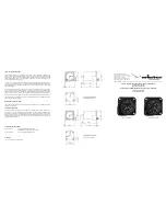
Page 106: ...ABX 3 MBX 3 Reference Manual 86 Figure A 1 External Signal Splitter ...

Page 107: ...de that is available on the Internet from the CSI Wireless home page www csi wireless com This listing contains the following information regarding currently operating beacons and potential new sites n Station name n Frequency n MSK rate n Location n Transmitting ID n Reference station ID n Field Strength n Operating notes ...

Page 108: ...ABX 3 MBX 3 Reference Manual 88 ...

Page 109: ...A Radio Technical Commission for Maritime Services RTCM Recommended Standards for Differential NAVSTAR GPS Service Version 2 2 Developed by Special Committee No 104 RTCM 1998 1800 Diagonal Rd Suite 600 Alexandria VA 22314 2840 USA Tel 1 703 684 4481 Fax 1 703 836 4429 US Department of Transportation United States Coast Guard Broadcast Standard for the USCG DGPS Navigation Service COMDTINST M16577 ...

Page 110: ...ntenna 7 19 20 MGL 3 Combination Antenna 8 19 Automatic Beacon Search ABS 6 37 42 50 Azimuth 40 B Background Search 25 30 Baud Rate 14 23 28 35 42 52 Beacon Command Center 46 Beacon Table User 30 37 43 World 30 37 43 C Cables Antenna 20 Data 12 Power 12 Connectivity 12 13 CSI Wireless Encryption 37 Customer Service xvi D Default Settings 23 28 DGPS Errors 3 Age of Correction 4 Atmosphere 4 Geometr...

Page 111: ... Splitter Option 22 K Keypad 23 27 L Latitude 38 Lock Status Beacon 28 GPS 31 Longitude 38 M Manual Tune Mode 6 MBA 3 Whip Antenna 7 17 MBL 3 Loop Antenna 7 19 20 Menu Tree 32 Beacon Status 32 Options 35 Position Status MBX E 38 Satellite Status MBX E 39 Setup 35 Start Up 32 Message Throughput MTP 34 MGL 3 Combination Antenna 8 19 Multipath 5 N NMEA 0183 6 45 NMEA 0183 Command 48 51 Automatic Beac...

Page 112: ...13 14 15 16 RS 422 Interface Level 12 14 15 16 RTCM Message Types 3 RTCM SC 104 3 6 12 45 S SBX 2 6 Select Beacon 37 Selective Availability SA 2 4 Signal Strength 34 Signal to Noise Beacon 34 GPS 40 Splitter 7 8 22 Subscription 37 SV Count 39 T Temperature 11 Time 39 Troubleshooting 61 62 Tune Mode Automatic 37 42 Manual 37 42 Tune Modes 24 29 Automatic 24 25 29 30 Manual 25 30 U U Bracket 10 UTC ...

Page 113: ...ABX 3 MBX 3 Reference Manual 93 ...

Reviews: