X-XX UL
INSTALLATION INSTRUCTIONS
CAUTION
Never use any source of power other than a self-
powered millivoltage pilot generator system.
NOTE:
The TS86 was carefully adjusted at the factory.
Handle the thermostat carefully
; rough handling
may decrease its accuracy.
Location
Select a location about 5 ft (1.5m) above the floor in an
area with good air circulation at average temperature.
Do not mount the thermostat where it can be affected by:
— drafts, or dead spots behind doors and in corners.
— hot or cold air from ducts.
— radiant heat from the sun or appliances.
— concealed pipes and chimneys.
— unheated (uncooled) areas behind the thermostat.
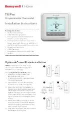
Mounting Wallplate on Wall
IMPORTANT
Use plumb line or spirit level to accurately level
wallplate (Fig. 1). Inaccurate wallplate leveling
causes the temperature control to deviate from
the setpoint.
Use 127293 Cover Ring and wallplate to mount on outlet
box as in Fig. 3. For wall mounting, use of 127293 Cover
Ring is optional (Fig. 2).
1. Place cover ring on the wall at the desired location
with the cable entrance holes to the left.
2. Bring the thermostat cable through the bottom
entrance hole of the cover ring and through the
wallplate entrance hole.
3. Fasten the cover ring and wallplate to the wall with
the mounting screws as shown in Fig. 2.
4. Tighten screws after the wallplate is leveled. See
Fig. 1 for leveling instructions.
TS86A
Powerpile
®
Thermostat
APPLICATION
The TS86A is a mercury switch thermostat that controls
Powerpile® millivolt gas systems. The millivolt system
operates independently of the electrical line service of the
home. Do not attach this thermostat to any source of
power other than a millivolt pilot generator.
The wallplate adapts the TS86A to 250, 500, or
750 millivolt systems.
The positive OFF switch on the TS86A breaks the
electrical circuit to prevent system operation.
RECYCLING NOTICE
This control contains mercury in sealed tube.
Do
not
place control in the trash at the end of its
useful life.
If this control is replacing a control that contains
mercury in a sealed tube, do
not
place your old
control in the trash.
Contact your local waste management authority
for instructions regarding recycling and the proper
disposal of this control or of an old control
containing mercury in a sealed tube.
INSTALLATION
When Installing this Thermostat…
1. Read these instructions carefully. Failure to follow
them could damage the thermostat or cause a
hazardous condition.
2. Check the ratings given in the instructions and on
the thermostat to make sure it is suitable for your
application.
3. Installer must be a trained, experienced service
technician.
4. After installation is complete, check out thermostat
operation as provided in these instructions.
®U.S. Registered Trademark
Copyright © 1995 Honeywell Inc. • • All Rights Reserved
69-0153-3