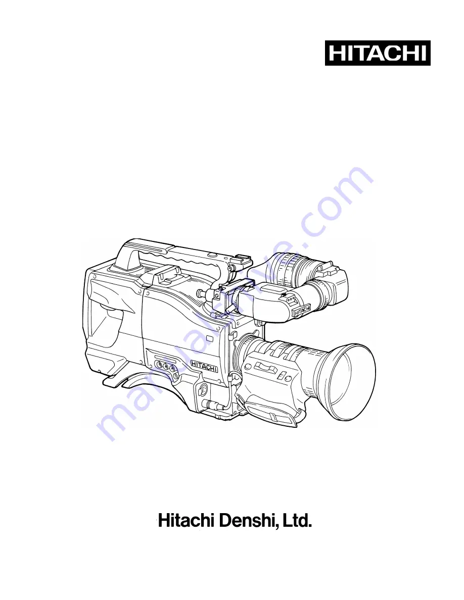
background image

DIGITAL CAMERA


S-3000W / S-3000

OPERATING INSTRUCTIONS

Please read this operating instructions carefully for proper operation,

Please read this operating instructions carefully for proper operation,

Please read this operating instructions carefully for proper operation,

Please read this operating instructions carefully for proper operation,
and keep it for future reference.

and keep it for future reference.

and keep it for future reference.

and keep it for future reference.

Summary of Contents for S-3000

Page 1: ...ad this operating instructions carefully for proper operation Please read this operating instructions carefully for proper operation Please read this operating instructions carefully for proper operation and keep it for future reference and keep it for future reference and keep it for future reference and keep it for future reference ...

Page 2: ...nstable cart stand tripod bracket or table The product may fall causing serious injury to a child or adult and serious damage to the product Use only with a cart stand tripod bracket or table recommended by the manufacturer or sold with the product Any mounting of the product should follow the manufacturer s instructions and should use a mounting accessory recommended by the manufacturer 9 Moving ...

Page 3: ...r short out parts that could result in a fire or electric shock Never spill liquid of any kind on the product 17 Inflammable and Explosive Substance 17 Inflammable and Explosive Substance 17 Inflammable and Explosive Substance 17 Inflammable and Explosive Substance Avoid using this product where there are gases and also where there are inflammable and explosive substances in the immediate vicinity...

Page 4: ...ty Check 22 Safety Check Upon completion of any service or repairs to this product ask the service technician to perform safety checks to determine that the product is in proper operating condition 23 Wall or Ceiling Mounting 23 Wall or Ceiling Mounting 23 Wall or Ceiling Mounting 23 Wall or Ceiling Mounting The product should be mounted to a wall or ceiling only as recommended by the manufacturer...

Page 5: ...ckens usw 8 Aufstellung 8 Aufstellung 8 Aufstellung 8 Aufstellung Das Erzeugnis nicht auf einen unstabilen Wagen Stand Dreifuß Träger oder Tisch stellen Das Erzeugnis kann sonst herunterfallen und ein kind oder einen Erwachsenen schwer verietzen Außerdem kann das Gerät schwer beschädigt werden Nur mit einem Wagen Stand Dreifuß Träger oder Tisch verwenden der vom Hersteller empfohlen oder mit dem E...

Page 6: ... lange Zeit den Stecker aus der Steckdose ziehen Dies verhütet Beschädigung durch Blitzschlag und Netzspannungsstöße 15 15 15 15 Überlastung berlastung berlastung berlastung Wandsteckdosen Verlängerungskabel und eingebaute Bequemlickkeitssteckdosen nicht überlasten da dies Feuer oder elektrischen Schlag verursachen kann 16 Eindringen von Fremdk 16 Eindringen von Fremdk 16 Eindringen von Fremdk 16 ...

Page 7: ...darauf hin daß Wartung erforderlich ist 21 Ersatzteile 21 Ersatzteile 21 Ersatzteile 21 Ersatzteile Wenn Ersatzteile erforderlich sind darauf achten daß der Wartungstechniker nur die vom Hersteller festgelegten Ersatzteile oder Teile mit den gleichen Charakteristiken wie die ursprünglichen Teile verwendet Unautorisierte Ersatzteile können Feuer elektrischen Schlag oder sonstige Gefährdungen verurs...

Page 8: ... instables L appareil pourrait tomber blessant griévement des enfants ou des adultes et étant sérieusement endommagé Utiliser exclusivement le chariot le socle le pied le support ou la table recommandés par le fabricant ou vendus avec l appareil Pour tout montage de l appareil respecter les instructions du fabricant et utiliser á cette fin l accessoire de montage recommandé par le fabricant 9 L 9 ...

Page 9: ...orte dans les ouvertures de l appareil car ils pourraient toucher des points de tension dangereuse ou court circuiter des piéces ce qui pourrait provoquer un feu ou un choc électrique Ne jamais renverser de liquide d aucune sorte sur l appareil 17 Substances inflammabes et explosives 17 Substances inflammabes et explosives 17 Substances inflammabes et explosives 17 Substances inflammabes et explos...

Page 10: ...e et autres dangers 22 V 22 V 22 V 22 Vérificaton de s rificaton de s rificaton de s rificaton de sécurit curit curit curité Aprés tout travail d entretien ou de réparation de l appareil demander au technicien de réparation d effectuer les vérifications de sécurité pour s assurer que l appareil est en bon état de marche 23 Montage au mur ou au plafond 23 Montage au mur ou au plafond 23 Montage au ...

Page 11: ... battery pack 21 GM 51 5inch viewfinder attachment 22 VTR connection 24 Power supply 27 Viewfinder adjustment 28 lris Adjustment 31 Zoom and Macro operation 32 Optical Filter Selection 33 Video Gain Selection 34 White and black balance adjustment 35 Electronic Shutter setting 40 Scene File 42 Camera ID setting 43 Genlock 44 Setup Card 45 Viewfinder Indications 48 Status Indication of Viewfinder Sc...

Page 12: ...1 Composition including accessories When unpacking the camera check for the following items and accessories ...

Page 13: ...it technology to a newly developed digital noise reduction circuit Even at high gain clear low noise images can be obtained Sensitivity standard 2000 lux F11 High gain 24 dB and Ultra Gain 12 dB can be combined for up to 36 dB gain increase Operation is enabled down to 0 5 lux F1 4 and 0 8 lux F1 8 Setup card Camera setup data can be saved to a setup card Compact Flash and recalled when required F...

Page 14: ...ined with VTR High performance viewfinder GM 9 With 600 TV lines resolution for easy focus adjustment Large aperture lens for comfortable eye relief Front rear left right and tilt mechanisms allow adjustment to best angle Bayonet mount for direct connection to camera without cable Rotate 90 degrees upward for convenient carrying New low CG design Main operation switches are grouped forward for eas...

Page 15: ...es Subject to strong vibration Humid or dusty locations Salt spray or corrosive gases Strong electromagnetic fields e g near TV or radio transmitters Where exposed to rain Do not cover or otherwise obstruct camera heat dissipation during operation WARNING Viewfinder high voltage Do not open the viewfinder cover There is danger of touching internal high voltage components CAUTION When connecting an...

Page 16: ...hen using a CCD camera for broadcast or other demanding applications Smear When a bright object is picked up thin trails appear above and below the image The effect is more pronounced at high electronic shutter speeds Fixed pattern When operate at high temperature a fixed pattern vertical stripes white dots can appear The pattern is more easily seen when the camera sensitivity is raised ...

Page 17: ... 6 Shoulder belt hook Attachment for separately sold shoulder belt 7 Talk on off switch Intercom microphone on off when connected into a system with the RU Z2 RU Z1 8 IIntercom level control Intercom sound level volume adjustment when connected into a system with the RU Z2 RU Z1 9 Power select switch BATT CCU VTR EXT BATT When power is supplied via the BATT12V IN connector CCU VTR When power is su...

Page 18: ...n to use the electronic shutter At the SEL position the shutter speed and mode are changed in the range set beforehand at the setting menu 14 CS 2 switch On off switching for function set at menu 15 Audio channel 1 recording level control The audio recording level can be adjusted only when connected to a Betacam VTR BVV 1 or BVV 5 16 VTR start button When connected to a VTR in the recording mode p...

Page 19: ...e viewfinder screen 20 White balance memory switch PRE Set to this position when circumstances such as time do not allow adjusting the white balance The white balance is set to the memory value for 3200 K A or B When the AUTO W B BAL switch 12 is set to AWB the white balance is adjusted automatically according to the Filter knob 4 setting The adjustment is stored in the selected memory A or B 21 O...

Page 20: ... buttons Change the setting selected by the Function button 26 In the lock scan mode use for adjusting the shutter speed 29 Ultra gain on off switch ON Increase sensitivity about 12 dB Operates only when the sensitivity is above 12 dB some loss of horizontal resolution OFF Normal mode operation 30 Digital noise reduction DNR on off switch ON Reduces noise during high gain OFF Normal mode operation...

Page 21: ...mote control panel or a personal computer 36 Microphone connector XLR 3P Connection for separately sold microphone Microphone power is supplied from this connector 37 Lens connector 12 pin Connection for lens cable 38 CCU VTR connector 28 pin for CA Z31 26 pin for CA Z32 Use separately sold cable to connect a portable VTR or RU Z1 RU Z2 RU Z3 camera base station 39 Lighting shoe screw hole 1 4 inc...

Page 22: ...ld AC adapter for operating from AC power 45 Intercom connector XLR 5P Connect intercom headset MT 12MF when using the RU Z1 RU Z2 RU Z3 46 150 V Out connector 5 pin CA Z32 only Connect 150 V to 12 V power supply adapter when using a large size lens 47 Audio monitor connector minijack Connect an earphone 8 to 10Ω to monitor microphone or VTR playback sound ...

Page 23: ...t Does not affect camera output signal 51 External tally switch ON External tally lamp lights OFF External tally lamp does not light 52 Camera connector Connects viewfinder to camera 53 Eyecup 54 Visibility adjust ring knob Adjust for best viewfinder image clarity according to the operator 55 Tightening ring Secures eyecup after adjusting the vertical angle 56 External tally indicator When the ext...

Page 24: ...ount and install the lens 3 Lower the lens lever to secure the lens 4 Engage the cable with the cable clamp and connect it to the lens connector Refer to the lens instructions when using the lens Notes The following adjustments may be required according to the type of lens 1 Lens flangeback 2 Lens auto iris speed 3 Lens white shading with camera ...

Page 25: ...ion 2 Open the iris Set a flangeback adjusting chart about 3 meters distant and adjust the lighting to obtain the correct video output level If the video level is too high use a CC ND filter or electronic shutter 3 Loosen the Ff ring setscrew 4 By hand or motor set the zoom ring to the telephoto position 5 Observe the flangeback chart image and turn the distance ring to adjust the focus 6 Set the ...

Page 26: ...f paper tends toward green at the top and magenta at the bottom or vice versa Adjustment steps 1 Install the lens on the camera be sure to connect the lens cable 2 Set the electronic shutter to off and the gain to L 0 dB 3 If provided set the lens extender to off 4 Notice that flicker can occur with fluorescent or mercury lighting Therefore use sunlight or halogen as the light source In the auto i...

Page 27: ...cate automatic white shading adjustment in progress The cursors extinguish at the end of adjustment 8 Set the extender if provided to on and repeat the above step 9 Close the Function menu White shading adjustment is completed by the above The adjustment is stored in a nonvolatile memory and ordinarily does not need to be repeated even if the power is switched off Notes 1 Precise adjustment may no...

Page 28: ... guide pin Attach the adapter and engage the connector 2 Tighten the screws provided with the handle to secure the camera adapter to the camera CAUTION Tighten the screws completely Check for absence of wobble between the camera and adapter 3 Install the handle with two screws ...

Page 29: ...amp and connect to the MIC IN connector Microphone power and sensitivity Set from Function 2 menu screen 1 Phantom power 48 V can be supplied Set to on for the MC Z2 Z3 or ME 66 Set to off for an internal battery or dynamic type microphone 2 Select the microphone sensitivity FUNCTION 2 M BLACK 0 DYNA CHROMA ON DNR MODE MODE1 ZEBRA TYPE 1 LEVEL MID CS 1 SW QUICK FOCUS CS 2 SW CONTRAST MIC SENSE MID...

Page 30: ... the arrow A click sound can be heard at the locked position 3 Slightly loosen the tripod screw and again check the balance Shift the adapter to the optimum position and securely tighten the tripod screw Detaching Press the red lock pin and turn the lever in the arrow direction Remove the camera CAUTION 1 The weight can exceed 5 kg with the lens and 10 kg with a VTR Use a sturdy tripod that can su...

Page 31: ...r pad can be shifted up to 15 mm in either direction from the center factory position The position can be adjusted for comfortable operation 1 Loosen 2 screws 2 Slide the pad forward or rearward to the best position 3 Tighten the 2 screws ...

Page 32: ... Insert and slide the battery pack 3 Set the camera adapter Power Select switch to BATT 4 To remove the battery set the battery holder detaching lever fully downward then slide the battery as shown by the arrow to remove it Note The intelligent ultra basketry can also be used The intelligent battery can automatically detect battery remaining of more than 10 The viewfinder indicates battery remaini...

Page 33: ...ure to tilt the lock lever forward and turn it clockwise to tighten it If tightening is overlooked the GM 51 can drop and pose a risk of injury 2 Insert the GM 51 and AT 30 into the slot at the rear of the handle and slide them forward until a latching sound is heard from the release knob Warning Press the release knob to where a latching sound is audible If not securely attached the entire viewfi...

Page 34: ...23 GM 51 5 inch viewfinder attachment 3 Removal Disconnect the viewfinder cable Turn the AT 30 lock lever B counter clockwise and pull the release knob to allow removing both the GM 51 and AT 30 ...

Page 35: ...VCAM Matsushita Panasonic AU 45H MⅡ Promind AJ D90 DVCPRO JVC BR S422 S VHS BR D40 DIGITAL S Required inner modules separately sold Note Refer to the VTR and inner module instructions for details regarding installation Note VTR examples are shown only for general reference Model names and specifications are subject to change ...

Page 36: ... DVCPRO COMP 60dB IM Z3P AJ D90 S VHS Y C 20dB IM Z3P BR S422 C 201TD C 301TF AG 7400 BR S400 DIGITAL S COMP 20dB IM Z3P BR D40 U matic VBS 60dB C 201TD C 301TF VO 8800 Note Set at the System sub menu of the Function menu screen When using a dockable VTR with inner module camera setting is unnecessary The System sub menu indicates Auto SYSTEM VF DTL CONT MENU VIDEO VTR AUTO AUDIO LEVEL AUTO CLOSE ...

Page 37: ...yback monitor When the VTR includes a recording review function in the VTR REC Pause mode press the lens RET button to view the final few seconds of the recording in the viewfinder By setting the VTR to the playback mode the playback image automatically appears in the viewfinder while the sound can be heard with an earphone If the VTR does not have a REC review function the playback mode image can...

Page 38: ... 12 to 13 VDC Voltage exceeding 17 VDC can cause damage 2 In not using the equipment for an extended period of time set the AC adapter switch to off If a battery is connected remove the battery Voltage down display As the voltage declines B lights in the viewfinder The System sub menu of the Special Set menu sets the battery type Alarm Set adjusts the voltage at which B lights Battery type Alarm o...

Page 39: ...re the viewfinder guide 2 Turn the viewfinder lock lever fully counter clockwise 3 Align the 2 viewfinder guide pins with the camera guide holes and insert the viewfinder 4 Secure the lock lever firmly in the arrow direction CAUTION Connect the viewfinder correctly and securely to the viewfinder connector ...

Page 40: ...direction to loosen the front to rear lock 3 Adjust the viewfinder left to right and front to rear positions for comfortable viewing 4 Tighten the lock screw firmly 5 Tighten the lock lever securely Eyepiece angle adjustment 1 Turn and loosen the securing ring 2 Adjust the eyepiece vertical angle for comfortable viewing 3 Firmly tighten the securing ring ...

Page 41: ...he camera Stand the viewfinder vertically as shown in the figure for ease of carrying about WARNING When the hood is raised do not look at the sun or other bright light through and eyepiece lens There is danger of eye damage When the hood is raised do not place the camera where sunlight can pass through the eyepiece lens There is risk of damage to the camera and peripheral equipment as well as a h...

Page 42: ...ng the button instantly and automatically adjusts the iris Notes 1 Set the iris response peak average from the Function 1 menu screen 2 While the menu screen is not displayed fine adjust the auto iris by pressing the buttons The adjustment range using the buttons is indicated below 1 0 0 8 0 6 0 4 0 2 0 0 2 0 4 0 6 0 8 1 0 Closed about 1 F stop Opened about 1 F stop The adjustment can be used if p...

Page 43: ...slow operation 2 Manual zoom Set the zoom switch to M manual and manually operate the zoom lever Macro operation Use this function when the camera subject is closer than 1 1 meters from the lens 1 Approach the camera subject for the required size image 2 Set the focus ring to infinity 3 Set the zoom switch to M 4 Set the macro ring to macro and fine adjust the focus with the zoom lever Note Focus ...

Page 44: ...eds to be selected in order to obtain correct white balance Set the CC ND filter knob as follows No Filter Light source 1 3 200K Studio tungsten or halogen Sunrise sunset 2 5 600K 1 16ND Outdoors clear sky 3 5 600K Fluorescent lighting Outdoor cloudy or rainy 4 5 600K 1 64ND Outdoors clear sky ...

Page 45: ...n the viewfinder to advise of high gain mode 3 Gain values at L M and H switch positions are set at the Function 1 page GAIN switch Gain value L LOW 3dB 0dB M MID 6dB 9dB 12dB H HIGH 12dB 18dB 24dB 4 ULTRA GAIN When the gain setting is above 12 dB set the Ultra Gain switch to on to increase the sensitivity about 12 dB further Notice this reduces the horizontal resolution by about half Normally set...

Page 46: ...ts 1 Set the switches indicated in the figure Select a Scene File from 1 to 4 Gain and White Balance switch settings are indicated on the viewfinder screen when VF Display menu is on 2 Set the Filter knob according to lighting conditions See Optical filter selection When changed the new setting is indicated in the viewfinder for about 3 seconds 3 Place a white pattern at a location subject to the ...

Page 47: ...adjustment value is automatically stored in the selected Scene File memory A or B AUTO WHITE Adjustment in progress AUTO WHITE OK FILTER 3200K C TEMP 3500K Adjustment complete Note Hunting can occur if an auto iris type zoom lens is used Adjust the lens iris gain see lens operating instructions Note 1 Hunting Undesirable oscillation of an automatic control system wherein the controlled variable sw...

Page 48: ...witch to M or H If manual iris lens adjust the lens Then repeat white balance adjustment AUTO WHITE NG LEVEL HIGH TRY AGAIN Excessive lighting for adjustment Set Gain switch to a lower position If manual iris lens adjust the lens Then repeat white balance adjustment AUTO WHITE NG C TEMP HIGH CHANGE FILTER TRY AGAIN Color temperature too high for adjustment Change optical filter and readjust AUTO W...

Page 49: ...justment 1 Set the switches as indicated in the figure 2 Set the Auto W B BAL switch to ABB and release the switch The switch returns to center for adjustment 3 The viewfinder displays the following messages during adjustment The lens iris is automatically closed 4 Adjustment is completed in several seconds and automatically stored in memory AUTO BLACK Adjustment in progress AUTO BLACK OK Adjustme...

Page 50: ...rror messages If auto black balance adjustment fails the following error messages appear on the viewfinder screen for about 6 seconds Message Cause Correction AUTO BLACK NG CHANGE TO CAM TRY AGAIN Output switch at BAR Change switch to CAM AUTO BLACK NG IRIS NOT CLOSE TRY AGAIN Iris is not closed See Note 1 AUTO BLACK TALLY ON EXECUTE Tally lamp lighted While lighted again set the Auto W B BAL swit...

Page 51: ... 2000 second 1H steps Reduce horizontal streaking in images of computer monitor CC FRM CC frame Increased vertical resolution Note Camera sensitivity declines as shutter speed increases An auto iris lens iris opens at increased shutter speed while the depth of focus decreases Shutter mode and speed settings 1 Shift the Shutter switch from ON to SEL to change the shutter speed The viewfinder screen...

Page 52: ...frequency includes a light or dark bar rolling up or down through the image Adjust the buttons to minimize the bar button Flicker free image Fast shutter speed Roll Dark Light Slow shutter speed button Roll Note Flicker cannot be corrected when the display screen scanning frequency is below 50 30 Hz CC frame mode Increases vertical resolution but sensitivity is reduced 1 F stop Operation with RU Z...

Page 53: ...WIDTH 128 127 2b White balance data each filter Remote mode 2c SHUTTER SELECT 1 100 1 250 Var AES CC FRM Setting steps 1 Select the file number with the Scene File switch adjust camera to the status previously stored in the memory 2 Set the file storage items if changing the memory contents a Set the Function 1 page items from the setting menu See page 45 b Operate auto white balance and store the...

Page 54: ...ID SET TIME DATE ID DSP ON DATE Y M D TIME ON AUDIO TONE ON ID SET ID NO 001 ID DISP HITACHI V 21 1234567890 ABCDEFGHIJKL MNOPQRSTUVWX YZ DEL INS RET While the cursor is at the ID SET line press the button to begin setting from ID No 1 setting position flashes Select the desired character with the buttons character flashes Press the FUNC button to enter the selected character character cursor shif...

Page 55: ...the GL SET page BAR FUNCTION GL SET ID SET TIME DATE ID DSP ON DATE Y M D TIME ON AUDIO TONE ON GL SET H PHASE 0 SC COARSE 0゚ SC FINE 0 3 Adjust the horizontal phase with H PHASE and the subcarrier phase with SC COARSE and SC FINE Connection example Note Genlock When two or more cameras and other equipment such as a special effect amplifier are connected into a system the horizontal sync and subca...

Page 56: ...rating error can occur Inserting Position the logo side upward insert the setup card and close the cover Note Observe the logo is face up and label is correctly oriented when inserting the card If difficult to insert the card is probably upside down or backwards Carefully check the card positioning when inserting Removal Open the cover by raising the bottom edge and press the button to remove the ...

Page 57: ...o is correct press the button for Yes If incorrect press the button for Cancel then set the correct File No The following message is indicated at the completion of save Press the button to return to the Memory Card Top menu then press the Function button to exit the menu SETUP CARD FILE NO DATE TIME 1 97 01 01 12 00 2 97 06 01 12 00 3 97 02 22 12 00 4 97 03 01 12 00 SAVE OK TOP MENU PUSH LEFT If S...

Page 58: ...1 97 01 01 12 00 2 97 06 01 12 00 3 97 02 22 12 00 4 97 03 01 12 00 SAVE OK TOP MENU PUSH LEFT Data load failure If Load Error is displayed at above step 5 data were not successfully loaded The card may be formatted incorrectly or defective Check and if there is no problem with the card consult a Hitachi Denshi service representative Formatting the card SETUP CARD FILE NO DATE TIME 1 97 01 01 12 0...

Page 59: ...tions Gain switch other than Low Shutter switch on Contrast Function 1 menu other than off Viewfinder screen indications CAM mode BAR mode Date time ID Check mode 1 line display mode Function mode Note Check mode is produced for about 3 seconds after pressing the Check button Then return to CAM mode Power switch on Output switch CAM or BAR 98 06 01 12 00 HITACHI Z 3000 Press Check button Press Fun...

Page 60: ... the top and bottom edges of the screen Messages regarding switch changes and adjustments are shown for about 3 seconds at the center of the screen CAM mode The above items are indicated only when set to on at the setting menu VF Display page Lens extender used Shutter speed Recording time Battery voltage or remaining amount Center marker Safety zone Filter position Ultra gain on Gain Audio level ...

Page 61: ...pplied to camera Battery remaining MAX 90 70 50 30 20 10 EMP Battery remaining amount indicated as a percentage when using Anton Bauer Digital Magnum series battery Filter position E 1 2 3 4 Error filter position not set correctly Filter 1 selected Filter 2 selected Filter 3 selected Filter 4 selected White BAL switch and full auto white balance A B P F White BAL switch position A White BAL switch...

Page 62: ... other switch setting states Display description Item Description DTL level DTL OFF 128 0 127 Flesh tone FLESH TONE ON OFF Masking MASKING OFF PRESET MEMORY Contrast CONTRAST OFF NORMAL HIGH Zebra type ZEBRA OFF TYPE1 LOW TYPE1 MID TYPE1 HIGH TYPE2 LOW TYPE2 MID TYPE2 HIGH CS 1 switch functions CS 1 CONTRAST QUICK FOCUS FULL AUTO CS 2 switch functions CS 2 CONTRAST QUICK FOCUS FULL AUTO E 1 60 10M...

Page 63: ...E FLESH TONE ON OFF DNR DNR ON OFF CS 1 CS 2 CONTRAST OFF NORMAL HIGH QUICK FOCUS ON OFF FULL AUTO ON OFF OUTPUT AUTO KNEE AUTO KNEE ON OFF CC ND FILTER FILTER 3200K 5600K 1 16ND 5600K 5600K 1 64ND IRIS 1 0 0 8 0 4 0 2 0 0 2 0 4 0 8 1 0 1 VAR select by Shutter switch SHUTTER Var 50 32 to 2092 V 21W 1 50 30 to 2053 V 21 1 1 Iris and Shutter settings only are displayed for about 6 seconds E 1 60 10M...

Page 64: ...53 Status Indication of Viewfinder Screen BARS mode Note Above items are set at the Function BAR mode menu 98 06 01 12 00 HTACHI Date Time ID ...

Page 65: ...king Masking adjustment DTL Detail adjustment Gamma Gamma adjustment Knee Clip Knee and white clip adjustments White Shading White shading adjustment Flare Flare adjustment System System adjustment Operation and menu screens Operation is from the function and direction buttons FUNC Function screen on off Change page when cursor is at 1st line When a sub menu is displayed press to return to the mai...

Page 66: ...INITIALIZE FULL AUTO SEL AES ON FAW ON FUNCTION 2 M BLACK 0 DYNA CHROMA ON DNR MODE MODE1 ZEBRA TYPE 1 LEVEL MID CS 1 SW QUICK FOCUS CS 2 SW CONTRAST MIC SENSE MID PHANTOM OFF F AUTO SEL DTL SCENE 1 DTL LEVEL 0 DTL FREQ STANDARD FLESH TONE LEVEL 128 AUTO SETUP PHASE 97 WIDTH 0 AUTO SETUP PUSH 1SEC VF DISPLAY SAFETY CENT BOTH EXTENDER ON UPPER MID SHT REC T UPPER RIGHT BATTERY FILTER ON WHITE BAL O...

Page 67: ...PECT 16 9 VF DTL CONT MENU VIDEO VTR COMP AUDIO LEVEL 60dB CLOSE LIMIT IRIS SPEED 0 REMOTE 9600BPS BATT TYPE 12V ALARM SET 11 5V Main menu FUNCTION 1 SCENE 1 CONTRAST OFF AUTO IRIS AVERAGE GAIN LOW 0dB MID 9dB HIGH 18dB DTL MASKING PRESET GAMMA PRESET INITIALIZE FUNCTION 2 M BLACK 0 DYNA CHROMA ON DNR MODE MODE1 ZEBRA TYPE 1 LEVEL MID CS 1 SW QUICK FOCUS CS 2 SW CONTRAST MIC SENSE MID PHANTOM OFF ...

Page 68: ...01 12 00 3 97 02 22 12 00 4 97 03 01 12 00 LOAD FILE YES PUSH RIGHT CANCEL PUSH UP SETUP CARD FILE NO DATE TIME 1 97 01 01 12 00 2 97 06 01 12 00 3 97 02 22 12 00 4 97 03 01 12 00 FORMAT FILE YES PUSH CHECK CANCEL PUSH UP Save execute Load execute Format execute SETUP CARD FILE NO DATE TIME 1 97 01 01 12 00 2 97 06 01 12 00 3 97 02 22 12 00 4 97 03 01 12 00 SAVE OK TOP MENU PUSH LEFT SETUP CARD FI...

Page 69: ...ONTH 01 DAY 01 HOUR 00 MINUTE 00 TIME DATE SET BAR FUNCTION GL SET ID SET TIME DATE ID DSP ON DATE Y M D TIME ON AUDIO TONE ON GL SET H PHASE 0 SC COARSE 0 ゚ SC FINE 0 ID SET ID NO 001 ID DISP 001 1234567890 ABCDEFGHIJKL MNOPQRSTUVWX YZ DEL INS RET Main menu Sub menu ...

Page 70: ...ght components LOW 3dB 0dB Select 3 dB or 0 dB local mode only GAIN MID 6dB 9dB 12dB Select 6 9 or 12 dB local mode only HIGH 12dB 18dB 24dB Select 12 18 or 24 dB local mode only DTL Display detail sub menu MASKING OFF PRESET MEMORY OFF Color correction off PRESET Standard type color correction MEMORY Color correction set at Masking sub menu GAMMA OFF PRESET MEMORY OFF Gamma set to 1 PRESET Standa...

Page 71: ...or 1 second to detect the color phase at the center of the image and set to the optimum position PHASE 128 0 97 127 Adjusts color phase to flesh tone The flesh tone detection range is indicated The indication signal is overlapped on the video output Use care not to operate this function while ON AIR WIDTH 128 0 127 2 Function 2 main menu M BLACK 128 0 127 Sets the master black value DYNA CHROMA OF...

Page 72: ...ub menu WHT SHADING Change screen to white shading sub menu FLARE Change screen to flare sub menu SYSTEM Change screen to system sub menu ALL INITIALIZE 4 1 Masking Memory sub menu HUE 128 127 R 25 G 0 B 52 Y 64 C 0 M 67 6 vector independent masking Adjust Hue and Saturation independently for red R yellow Y green G cyan C blue B and magenta M SAT 128 127 R 16 G 0 B 0 Y 60 C 18 M 0 LINEAR 128 0 127...

Page 73: ...IALIZE Simultaneously press the buttons to initialize DTL sub menu items to values shown in rectangles 4 3 Gamma Memory sub menu GAMMA TABLE A B C Selects gamma rise inclination Special gamma A Standard value B Reduces dark component gradation C Raises dark component gradation TOTAL GAMMA 128 0 127 Gamma correction can be changed from the standard setting R ADJUST 128 0 127 Total R and B gamma can...

Page 74: ...r on and off AUTO SETUP Automatic white shading adjustment Start by adjusting the green channel shading with MANU G ADJ Next adjust the auto white by pushing the button for 1 second Then adjust the auto white by pushing the button for 1 second MANU R ADJ 128 0 127 Use when adjusting white shading manually G ADJ 128 0 127 B ADJ 128 0 127 INITIALIZE Simultaneously press the buttons to initialize Whi...

Page 75: ...erates when the light is greater than the close limit value When the cursor is shifted to Close Limit the lens iris is automatically set to the close limit value When replacing the lens set the value to F16 IRIS SPEED 128 0 127 Adjust when using a 6 pin type lens for a 12 pin type use adjustment provided with the lens The auto iris response speed increases toward the side Adjust to where hunting d...

Page 76: ...ring genlock operation SC COARSE 0 90 180 270 Adjust subcarrier coarse during genlock operation SC FINE 128 127 Adjust subcarrier fine during genlock operation 5 2 ID SET sub menu ID No 3 place alphanumeric code Set camera identification number and a desired title ID DISP Up to 14 place alphanumeric code See page 44 5 3 TIME DATE sub menu YEAR 00 99 MONTH 01 12 DAY 01 31 HOUR 00 23 MINUTE 00 59 TI...

Page 77: ...B C 103KAB Camera base station RU Z2 RU Z3 5 inch view finder GM 51 View finder adaptor AT 30 Camera adaptor CA Z32 Junction unit JU Z2 Camera control panel RC Z2A RC Z21A RC Z3 1 5 inch view finder GM 9 Lens cable kit Extention adaptor EA Z3 Battery mount for ANTON BAUER QR DP800 AC adaptor Battery mount for NP 1 series Battery mount for BP 90 Camera head Headset Refer to the RU Z2 Z3 Camera Base...

Page 78: ...he JU Z2 Junction Unit is required Since camera control software is not supplied refer to the protocol technical data and compile a suitable program according to the computer being used Technical data are available regarding the software protocol for controlling the camera Please consult a Hitachi Denshi representative Technical data 1 Remote control protocol 2 Remote control command list ...

Page 79: ...C 103KR Remote operation uinit RU Z1 5 inch view finder GM 51 View finder adaptor AT 30 Camera adaptor CA Z31 Camera control panel RC Z1 RC Z11 1 5 inch view finder GM 9 Lens cable kit Battery mount for ANTON BAUER QR DP800 AC adaptor Battery mount for NP 1 series Battery mount for BP 90 Camera head Headset Refer to the RU Z1 Remote Operation Unit and RC Z1A Z11A operation manuals for detailed ope...

Page 80: ...Z1 Z2A Z3 remote control is off settings can be changed at the camera head full menu Settings are stored as common setting values in the RU Z1 Z2 Z3 RC Z1 Z2A Z3 memory 3 With RU Z1 Z2A Alarm Set is fixed at 11 0 V 4 When Auto is indicated settings are automatic at the inner module RU Z2 RU Z1 RGB connector signal output The signals indicated in the table can be selected for output from the RU Z2 ...

Page 81: ...Z32 Betacam adaptor IM Z3B Triax adaptor CX Z3 Junction unit JU Z2 Camera control panel RC Z1 RC Z11 Camera control panel RC Z2A RC Z21A RC Z3 Betacam SP Betacam SX DVCAM inner module IM Z3S PVV 3 DSR 1 Digital S inner module IM Z3J BR D40 BR S422 1 5 inch view finder GM 9 Lens cable kit Betacam MII S VHS U matic VTR cable C 201TE VTR cable C 201TB C 501TB VTR cable C 201TD C 501TD VTR cable C 301...

Page 82: ...male 1 2 3 4 11 5 7 12 6 8 9 10 C B H E F D A G Pin Signal 1 9V output 2 SD input 3 SD output 4 SD ground Pin Signal 1 MIC GND 2 MIC H IN 3 MIC C IN Pin Signal 1 AUX SW 2 CALL TRG 3 GND 4 ENF AUTO 5 IRIS CONTROL 6 12V 7 IRIS POSITION 8 NC 9 NC 10 NC 11 NC 12 NC Pin Signal A B LED C B LED C VF 9V D 12V E S LED F VF VIDEO Y G GND H T LED ...

Page 83: ...72 Camera adapter CA Z31 CA Z32 DC IN 4 pin male INTERCOM 5 pin male 1 2 3 4 1 5 3 4 2 Pin Signal 1 SHIELD 2 T 3 GND 4 R 5 R Pin Signal 1 GND 2 NC 3 NC 4 12V input ...

Page 84: ...1 4 R R Y C 18 CALL TRIG 5 VTR TRG 19 SYNC CHR 6 REC TALLY 20 AUX GND 7 G Y VBS 21 SYNC CHR GND 8 B B Y 22 INCOM L2 9 AUDIO 23 SD 10 AUDIO 24 AUX VIDEO Pin Signal Pin Signal A 150V 12V 12 PROMPT GND VTR TRIG B POWER GND 13 PROMPT VIDEO BATT ALM 1 VBS 14 INTER LOCK TAPE IND 2 VBS GND 15 INCOM2 REC TALLY 3 G Y VBS GND 16 GL RET V CONT 4 G Y VBS 17 INCOM GND 5 R R Y C 18 AUX VIDEO PB VIDEO 6 R R Y C ...

Page 85: ...NOTE Notes indicate an area or subject of special merit emphasizing either the product s capabilities or common errors in operation or maintenance WARNING TO REDUCE THE RISK OF FIRE OR ELECTRIC SHOCK DO NOT EXPOSE THIS COLOR CAMERA TO RAIN OR MOISTURE AVERTISSEMENT Afin d éviter tout risque d incendie ou d électrocution ne pas exposer l appareil á la pluie ou á l humidité Afin d écarter tout risqu...

Page 86: ...ADA M1V 5J3 Phone 416 299 5900 FAX 416 299 0450 Eastern Office 5795 Chemin St Francois St Laurent Quebec CANADA H4S 1B6 Phone 514 332 6687 FAX 514 335 1664 Ottawa Office 9 Antares Drive Nepean Ontario K2E 7V5 Canada Phone 613 727 3930 FAX 613 825 4253 HITACHI DENSHI EUROPA GmbH Head Office Wesikircher Straße 88 Jüesheim D 63110 Rodgau Germany Phone 06106 6992 0 FAX 06106 16906 HITACHI DENSHI U K L...

Reviews: