


$:'8%
$:'8%
$:'8%
$:"8%"8%
/MV4000E
March 2006
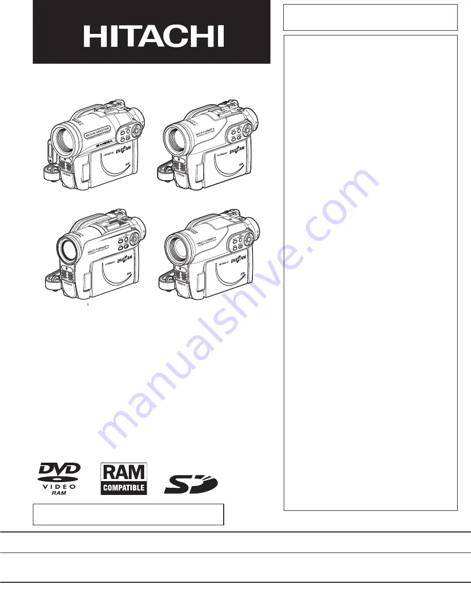
SERVICE MANUAL
SPECIFICATIONS AND PARTS ARE SUBJECT TO CHANGE FOR IMPROVEMENT
DVD VIDEO CAMERA/RECORDER
SM0603
DZ-GX3300E
DZ-GX3300E(UK)
DZ-GX3300E(AU)
DZ-GX3300E(SW)
DZ-GX3300E(SWC)
DZ-GX3300E(SWH)
DZ-GX3200E
DZ-GX3200E(UK)
DZ-GX3200E(AU)
DZ-GX3200E(SW)
DZ-GX3200E(SWC)
DZ-GX3200E(SWH)
DZ-GX3100E
DZ-GX3100E(UK)
DZ-GX3100E(AU)
DZ-GX3100E(SW)
DZ-GX3100E(SWC)
DZ-GX3100E(SWH)
DZ-BX37E
DZ-BX37E(UK)
DZ-BX37E(AU)
DZ-BX37E(SW)
DZ-BX37E(SWC)
DZ-BX37E(SWH)
DZ-BX35E
DZ-BX35E(UK)
DZ-BX35E(AU)
DZ-BX35E(SW)
DZ-BX35E(SWH)
DO NOT RESELL OR DIVERT IMPROPERLY


