background image

COPYRIGHT © DECEMBER, 2014 BY GRIZZLY INDUSTRIAL, INC. REVISED MARCH, 2019 (KB)

WARNING: NO PORTION OF THIS MANUAL MAY BE REPRODUCED IN ANY SHAPE

 OR FORM WITHOUT THE WRITTEN APPROVAL OF GRIZZLY INDUSTRIAL, INC.


(FOR MODELS MANUFACTURED SINCE 05/18) #WK16957 PRINTED IN CHINA

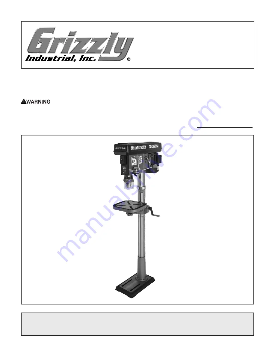
The Model G0794 is the same machine as the Model G7944, except the G0794 has a digital readout for 
spindle downfeed, and it is equipped with a laser drilling guide in place of the work light. Aside from the dif-
ferences noted in this insert, all other content in the Model G7944 owner's manual applies to this machine.

To reduce the risk of serious injury, you MUST read and understand this insert—and 

the entire Model G7944 manual—BEFORE assembling, installing, or operating this machine!

If you have any further questions about this manual insert or the differences between the Model G0794 
and the Model G7944, contact our Technical Support at (570) 546-9663 or email [email protected].

MODEL G0794

FLOOR DRILL PRESS 

WITH LASER AND DRO

MANUAL INSERT

Summary of Contents for G7943

Page 1: ...laser drilling guide in place of the work light Aside from the dif ferences noted in this insert all other content in the Model G7944 owner s manual applies to this machine To reduce the risk of serious injury you MUST read and understand this insert and the entire Model G7944 manual BEFORE assembling installing or operating this machine If you have any further questions about this manual insert o...

Page 2: ... Must Ship Upright No Electrical Power Requirement 110V Single Phase 60 Hz Full Load Current Rating 9A Minimum Circuit Size 15A Connection Type Cord Plug Power Cord Included Yes Power Cord Length 8 1 2 ft Power Cord Gauge 18 AWG Plug Included Yes Included Plug Type 5 15 Switch Type Paddle Safety Switch w Removable Key Motors Main Horsepower 3 4 HP Phase Single Phase Amps 9A Speed 1720 RPM Type TEF...

Page 3: ... Travel Crank Handle Operation Number of T Slots 4 T Slot Size 5 8 in T Slot Centers 3 7 8 in Floor To Table Height 20 46 in Construction Table Precision Ground Cast Iron Column Steel Spindle Housing Cast Iron Head Cast Iron Base Cast Iron Paint Type Finish Enamel Other Related Information Base Length 18 in Base Width 11 in Mobile Base D2260A Column Diameter 3 150 in Depth Stop Type Hub Other Spec...

Page 4: ...ISCONNECT DRILL PRESS FROM POWER 2 Install drill bit in chuck see Installing Removing Drill Bits on Page 25 of Model G7944 manual 3 Clamp workpiece securely to table 4 Adjust table so workpiece is within range of drill bit then lock table in horizontal position 5 Lower drill bit so it touches workpiece mak ing a slight indentation in the surface then raise bit 6 Connect drill press to power Turn l...

Page 5: ...stall DRO unit and DRO housing mak ing sure to re install shoulder screw from Step 2 The model G0794 is equipped with a digital read out DRO for precision spindle adjustment The DRO is independently powered by a SR44 but ton cell battery which may need to be changed from time to time Follow the instructions below to change the battery Tools Needed Qty Phillips Head Screwdriver 2 1 To change DRO ba...

Page 6: ...iagrams is current at the time of printing but may not match your machine If you find this to be the case use the wiring diagram inside the motor junction box CAPACITORS INVERTERS Some capacitors and power inverters store an electrical charge for up to 10 minutes after being disconnected from the power source To reduce the risk of being shocked wait at least this long before working on capacitors ...

Page 7: ...Motor Junction Box LR44 Battery Neutral Hot Ground 110 VAC 5 15 Plug Laser ON OFF Switch KDC01 101 2 8A 250VDC 1 1A S Capacitor 125VAC 200uF IN 120VAC OUT 3VDC TRANSFORMER GAO YOU Start Capacitor Figure 7 Start capacitor G0794 Wiring Laser Figure 6 Laser and transformer Transformer Figure 8 Motor junction box and terminal block Ground To Motor From Plug ...

Page 8: ... 41 42 43 44 45 46 48 49 50 51 52 53 54 55 56 56 28 57 58 58 1 58 2 58 3 58 4 58 6 58 7 58 8 58 9 58 10 59 60 61 62 63 64 65 66 67 68 144 69 70 71 72 73 74 75 76 77 78 79 80 81 82 83 84 85 86 87 88 89 90 91 92 97 98 99 100 104 105 101 119 102 103 110 113 115 116 120 121 122 123 124 125 126 127 128 129 130 131 132 133 134 135 136 136 137 137 138 58 11V2 ...

Page 9: ...CR M6 1 X 10 26 P0794026 DOWNFEED HANDLE M12 1 75 MALE 70 P0794070 PHLP HD SCR M5 8 X 10 27 P0794027 DOWNFEED KNOB M12 1 75 FEMALE 71 P0794071 FLAT WASHER 5MM 28 P0794028 LOCK WASHER 12MM 72 P0794072 PULLEY COVER KNOB M5 8 29 P0794029 KNOB BOLT M8 1 25 X 22 73 P0794073 PULLEY COVER 30 P0794030 SET SCREW M10 1 5 X 12 74 P0794074 V BELT M25 32 P0794032 EXT RETAINING RING 16MM 75 P0794075 PULLEY NUT ...

Page 10: ...ECTING PLATE 113 P0794113 ANGLE SCALE 131 P0794131 HEX NUT M3 5 115 P0794115 CAP SCREW M8 1 25 X 20 132 P0794132 PHLP HD SCR M3 5 X 10 116 P0794116 STRAIN RELIEF 1 4 5 16 ST PLASTIC 133 P0794133 LASER LIGHT RETAINING PLATE 118 P0794118 ANGLE INDICATOR 134 P0794134 PHLP HD SCR M5 8 X 8 119 P0794119 MOTOR LABEL 135 P0794135 LASER TRANSFORMER BRACKET 120 P0794120 CRANK LEVER 136 P0794136 PHLP HD SCR ...

Page 11: ...MUST replace it in the original location before resuming operations For replacements contact 800 523 4777 or www grizzly com Labels Cosmetics REF PART DESCRIPTION REF PART DESCRIPTION 139 P0794139 ELECTRICITY LABEL 142 P0794142 MACHINE ID LABEL 140 P0794140 READ ENTANGLE GLASSES LABEL 143 P0794143 MODEL NUMBER LABEL 141 P0794141 POWER PINCH HAZARD LABEL 139 143 139 140 141 139 142 ...

Page 12: ... 12 Model G0794 Mfd Since 05 18 ...

Page 13: ...NING NO PORTION OF THIS MANUAL MAY BE REPRODUCED IN ANY SHAPE OR FORM WITHOUT THE WRITTEN APPROVAL OF GRIZZLY INDUSTRIAL INC BL3698 PRINTED IN CHINA 184841 MODEL G7943 G7944 12 SPEED DRILL PRESSES OWNER S MANUAL For models manufactured since 09 17 V3 05 18 G7943 G7944 ...

Page 14: ...ng grinding tool integrity and the usage of personal protective equipment The manufacturer will not be held liable for injury or property damage from negligence improper training machine modifications or misuse Some dust created by power sanding sawing grinding drilling and other construction activities contains chemicals known to the State of California to cause cancer birth defects or other repr...

Page 15: ...sembly 20 Joining Drill Chuck Arbor 24 Test Run 25 SECTION 4 OPERATIONS 26 Operation Overview 26 Choosing Speeds 27 Changing Speeds 28 Drilling 29 Installing Removing Drill Bits 30 Depth Stop 30 Positioning Table 31 Removing Arbor 32 SECTION 5 ACCESSORIES 33 SECTION 6 MAINTENANCE 35 General 35 Cleaning Protecting 35 Lubrication 35 V Belts 35 SECTION 7 SERVICE 36 Troubleshooting 36 Calibrating Dept...

Page 16: ...ghtly different than shown in the manual If you find this to be the case and the difference between the manual and machine leaves you confused or unsure about something check our website for an updated version We post current manuals and manual updates for free on our web site at www grizzly com Alternatively you can call our Technical Support for help Before calling make sure you write down the M...

Page 17: ...uctions in this manual To reduce your risk of serious injury read this entire manual BEFORE using machine A ON OFF Switch B Light Switch C Belt Tension Lever D Belt Tension Lock E Table Height Crank F Table Rotation Lock Lever G Spindle Return Spring H Depth Stop I Chuck Guard J Scale K Column Lock Lever F E A B C D J H G D K I Right Side Controls Left Side Controls ...

Page 18: ...ess which houses the quill and work light and supports the motor and belt housing D Belt Tension Lever Adjusts motor location to increase decrease belt tension H Spindle Return Spring Automatically returns quill into headstock I Depth Stop Limits quill travel to a pre set drilling depth J Quill Houses the spindle and bearings K Chuck Accepts drill bits with shanks from 3 64 to 5 8 and uses a JT 3 ...

Page 19: ...pping Dimensions Carton 1 Type Cardboard Box Content Machine Weight 84 lbs Length x Width x Height 30 x 18 x 12 in Must Ship Upright No Carton 2 Type Cardboard Box Content Base Weight 64 lbs Length x Width x Height 33 x 26 x 9 in Must Ship Upright No Electrical Power Requirement 120V Single Phase 60 Hz Prewired Voltage 120V Full Load Current Rating 7 5A Minimum Circuit Size 15A Connection Type Cor...

Page 20: ...t Right 90 deg Table Swing 360 deg Table Swivel Around Center 360 deg Table Swivel Around Column 360 deg Max Movement of Work Table 12 1 2 in Table Length 11 3 8 in Table Width 11 3 8 in Table Thickness 1 1 4 in Vertical Table Travel Crank Handle Operation Number of T Slots 4 T Slot Size 1 2 in T Slot Centers 3 7 8 in Floor To Table Height 9 1 2 22 in Construction Table Precision Ground Cast Iron ...

Page 21: ...ectrical Power Requirement 120V Single Phase 60 Hz Prewired Voltage 120V Full Load Current Rating 7 5A Minimum Circuit Size 15A Connection Type Cord Plug Power Cord Included Yes Power Cord Length 8 1 2 ft Power Cord Gauge 18 AWG Plug Included Yes Included Plug Type 5 15 Switch Type Paddle Safety Switch w Removable Key Motors Main Horsepower 3 4 HP Phase Single Phase Amps 7 5A Speed 1725 RPM Type T...

Page 22: ...Height 20 1 4 46 in Construction Table Precision Ground Cast Iron Column Steel Spindle Housing Cast Iron Head Cast Iron Base Cast Iron Paint Type Finish Enamel Other Related Information Base Length 18 in Base Width 11 in Mobile Base D2260A Column Diameter 3 150 in Depth Stop Type Hub Has Work Light Yes Light Socket Type 120V Std Bulb Maximum Bulb Wattage 60 W Other Specifications Country of Origin...

Page 23: ... kid proof DANGEROUS ENVIRONMENTS Do not use machinery in areas that are wet cluttered or have poor lighting Operating machinery in these areas greatly increases the risk of accidents and injury MENTAL ALERTNESS REQUIRED Full mental alertness is required for safe operation of machin ery Never operate under the influence of drugs or alcohol when tired or when distracted For Your Own Safety Read Ins...

Page 24: ...with moving parts or flying debris Make sure they are properly installed undamaged and working correctly BEFORE operating machine FORCING MACHINERY Do not force machine It will do the job safer and better at the rate for which it was designed NEVER STAND ON MACHINE Serious injury may occur if machine is tipped or if the cutting tool is unintentionally contacted STABLE MACHINE Unexpected movement d...

Page 25: ...sharpness chips or cracks before each use Replace dull chipped or cracked bits cutting tools immediately EYE FACE HAND PROTECTION Flying chips created by drilling can cause eye injuries or blind ness Always wear a face shield in addition to safety glasses Always keep hands and fingers away from drill bit cutting tool Avoid awkward hand positions where a sudden slip could cause hand to move into bi...

Page 26: ...o an undersized circuit To reduce the risk of these hazards avoid over loading the machine during operation and make sure it is connected to a power supply circuit that meets the specified circuit requirements For your own safety and protection of property consult an electrician if you are unsure about wiring practices or electrical codes in your area Note Circuit requirements in this manual apply...

Page 27: ...n cord size gets longer and the gauge size gets smaller higher gauge numbers indicate smaller sizes Any extension cord used with this machine must be in good condition and contain a ground wire and matching plug receptacle Additionally it must meet the following size requirements Minimum Gauge Size 14 AWG Maximum Length Shorter is Better 50 ft Grounding Plug Requirements Figure 3 Typical 5 15 plug...

Page 28: ...for safe transport When unpacking separate all enclosed items from packaging materials and inspect them for shipping damage If items are damaged please call us immediately at 570 546 9663 IMPORTANT Save all packaging materials until you are completely satisfied with the machine and have resolved any issues between Grizzly or the shipping agent You MUST have the original pack aging to file a freigh...

Page 29: ...mm 1 Hex Bolt M10 1 5 x 25mm 4 Inventory The following is a list of items shipped with your machine Before beginning setup lay these items out and inventory them If any non proprietary parts are missing e g a nut or a washer we will gladly replace them or for the sake of expediency replacements can be obtained at your local hardware store NOTICE If you cannot find an item on this list care fully c...

Page 30: ...ather the following Disposable rags Cleaner degreaser WD 40 works well Safety glasses disposable gloves Plastic paint scraper optional Basic steps for removing rust preventative 1 Put on safety glasses 2 Coat the rust preventative with a liberal amount of cleaner degreaser then let it soak for 5 10 minutes 3 Wipe off the surfaces If your cleaner degreas er is effective the rust preventative will w...

Page 31: ... Environment The physical environment where the machine is operated is important for safe operation and lon gevity of machine components For best results operate this machine in a dry environment that is free from excessive moisture hazardous chemi cals airborne abrasives or extreme conditions Extreme conditions for this type of machinery are generally those where the ambient temperature range exc...

Page 32: ...ith the floor surface making it easy to unbolt and move the machine later if needed However anytime local codes apply you MUST follow the anchoring methodology specified by the code Machine Base Concrete Lag Screw Lag Shield Anchor Flat Washer Drilled Hole Figure 8 Popular method for anchoring machinery to a concrete floor Anchoring to Concrete Floors Number of Mounting Holes 4 Diameter of Mountin...

Page 33: ...ge footprint base plate when used with a mobile base Failure to use a base plate greatly increases pos sibility of tipping and personal injury Mounting G7944 to Mobile Base Items Needed Qty Plywood 3 4 x 23 3 4 x 233 4 2 Wood Glue As Needed Wood Screws 6 x 11 4 24 Hex Bolts 21 4 Long Sized for Base Plate 4 Hex Nuts Sized for Hex Bolts 4 Lock Washers Sized for Hex Bolts 4 Flat Washers Sized for Hex...

Page 34: ...rop erly assemble your drill press To assemble the machine 1 Place column on base and align mounting holes 2 Secure column to base with 4 hex bolts as shown in Figure 12 Figure 12 Column secured to base x 4 7 With help of an assistant place drill press on base plate 8 Position drill press close to front of mobile base so mobile base will not become a trip ping hazard 9 Mount drill press to base pl...

Page 35: ... column ring orientation 6 Place rack inside of table support assembly mesh it with pinion and slide table support rack assembly over column as shown in Figure 15 7 Slide column ring over column with beveled edge facing down as shown in Figure 16 then fit beveled edge of column ring over rack and tighten set screw Note Do not overtighten the set screw or you may split the column ring Also make sur...

Page 36: ...do you could damage the headstock and the column 11 Thread small lock lever into front part of table support assembly approximately three turns for now The assembly should match what is shown in Figure 17 Note For Model G7943 perform Steps 12 13 then proceed to Step 17 to complete assembly For Model G7944 proceed to Step 14 to complete assembly The headstock is very heavy You MUST have assistance ...

Page 37: ...rd place chuck guard over flange of depth gauge mount as shown in Figure 21 then tighten Phillips head screw and hex nut to secure it Note To prevent the guard from slipping off move the table up to support it Or have an assistant hold the guard in place while you secure it Figure 21 Installing chuck guard assembly Depth Gauge Mount 23 Thread handles into spindle hub as shown in Figure 22 and tigh...

Page 38: ...uck 4 Hold assembly by the arbor and tap chuck onto a block of wood with medium force as illustrated below Figure 25 Tapping drill chuck arbor on block of wood 5 Attempt to separate drill chuck and arbor by hand if they separate repeat Steps 3 4 25 Insert table shaft into table support assembly 26 Tighten small locking lever to secure table in table support assembly The table should now be install...

Page 39: ...derstanding its controls and related safety information DO NOT operate or allow others to operate machine until the information is understood To test run the machine 1 Clear all setup tools away from machine 2 Connect machine to power supply 3 Turn machine ON verify motor operation and then turn machine OFF The motor should run smoothly and without unusual problems or noises 5 Try to start machine...

Page 40: ...rpose of this overview is to provide the nov ice machine operator with a basic understanding of how the machine is used during operation so the machine controls components discussed later in this manual are easier to understand Due to the generic nature of this overview it is not intended to be an instructional guide To learn more about specific operations read this entire manual seek additional t...

Page 41: ...num Mild Steel 3 8 1 2 1200 1000 5 8 1 800 600 Using the Drill Bit Speed Chart The chart shown in Figure 27 is intended as a guide only Always follow the manufacturer s speed recommendations if provided with your drill bits cutters or hole saws Exceeding the recommended speeds may be dangerous to the operator The speeds shown here are intended to get you started The optimum speed will always depen...

Page 42: ...CHINE FROM POWER 2 Loosen the belt tension lock knobs shown in Figure 28 on both sides of the headstock so the motor is free to move Changing Speeds 3 Rotate the belt tension lever clockwise as shown in Figure 29 to take tension off the V belts 4 Locate the desired speed on the speed chart under the belt cover and move the V belts to the desired V grooves on the motor idler and spindle pulleys For...

Page 43: ...er to the Drill Bit Speed Chart on Page 27 to help you choose the correct speed for your application LARGE DIAMETER BITS Large diameter drill bits require slower spindle speeds SMALL DIAMETER BITS Smaller diameter drill bits require faster spindle speeds HARD MATERIAL Harder materials steel vs wood require slower drilling speeds Drilling SOFT MATERIAL Soft materials require a faster drilling speed...

Page 44: ...he depth nut Note The scale on the depth stop can be recalibrated if it gets moved or has changed since the factory setting Refer to Calibrating Depth Stop on Page 38 for instructions on how this is done Any drill bit you install in the chuck must be tight enough that it will not come loose during operation Installing Removing Drill Bits Stop Bracket Jam Nut Depth Nut Depth Stop Stud Installing a ...

Page 45: ...ten the table rotation lock lever Table Tilt 1 Tighten the location pin nut to draw the loca tion pin out of the hole Note The location pin is friction fit in the hole to lock the table at 0 When reinstalling set the table to 0 back the nut off and tap the pin back in the hole 2 Loosen the lock bolt and tilt the table to the desired angle make sure the small lock lever is locked so the table won t...

Page 46: ...quill 3 Loosen the lock knob and rotate the hub clockwise see Figure 33 until it stops Removing Arbor 8 Tap the drift key with a rubber or wooden mallet as shown in Figure 35 until the chuck releases 7 Insert the drift key into the drift key slot and allow the quill to rise trapping the drift key 9 Hold a downfeed handle with one hand and loosen the depth stop lock with the other hand 10 Carefully...

Page 47: ... popular 1 2 x 1 2 3 4 x 1 1 x 1 11 2 x 11 2 and 2 x 11 2 sizes Comes with 50 80 and 120 grit sizes for each drum Figure 36 Model G2500 20 Pc Sanding Drum Set G5753 Drill Press Vise 6 If you use a drill press and value your fingers you need one of these Made from high grade cast iron these hefty horizontal vises offer support and stability allowing you to keep your hands well away from fast moving...

Page 48: ...of time and money in the workshop Includes 1 16 3 8 bits and a heavy gauge steel index case for storage Figure 41 Model D2139 21 Pc Alloy Drill Bits Figure 42 Model G8581 1 2 Keyless Drill Chuck JT 33 G8581 1 2 Keyless Drill Chuck JT 33 Industrial grade keyless chucks are excellent for quick bit changes Knurled grips and exceptional accuracy make these chucks an indispensable part of any shop 0 1 ...

Page 49: ...ed cast iron table by wiping it clean after every use this ensures moisture from wood dust does not remain on bare metal surfaces Keep the table rust free with regular applications of products like G96 Gun Treatment SLIPIT or Boeshield T 9 see Page 33 for more details Cleaning Protecting For optimum performance from this machine this maintenance schedule must be strictly followed Ongoing To mainta...

Page 50: ...ne stalls or is underpowered 1 Incorrect dull cutter bit for task 2 Feed rate cutting speed too fast 3 Belt s slipping 4 Machine undersized for task 5 Motor overheated 6 Pulley slipping on shaft 7 Centrifugal switch at fault 8 Motor at fault 1 Use correct cutter bit 2 Decrease feed rate cutting speed Page 28 3 Ensure belts are oil free tension replace belt s ensure pulleys are aligned 4 Perform op...

Page 51: ...tock is hard to raise 1 Headstock lock nuts at fault 2 Rack and pinion at fault or jammed with grime debris 1 Loosen replace lock nuts 2 Fix replace broken or loose parts clean and lubricate rack and pinion Bad surface finish 1 Spindle speed too fast for workpiece material 2 Dull or incorrect cutting tool 3 Wrong rotation direction of cutting tool 4 Workpiece not secure 5 Spindle extended too far ...

Page 52: ...g Spindle Return Spring The tension of the spindle return spring makes the spindle automatically return to the top starting position when the downfeed handle is released This spring is pre adjusted at the factory and typically will never need further adjustment during the life of the drill press However additional tension can be applied if the spindle stops automatically returning to the top posit...

Page 53: ... Rotate the cover counterclockwise to increase spring tension or let the cover slowly unwind in the clockwise direction to reduce spring tension see Figure 45 7 Engage the next available spring cover lock slot with the locking lug and hold the spring lock cover tightly against the side of the headstock 8 Snug the cover nut against the spring cover just until the nut stops and then back off the nut...

Page 54: ...rrent at the time of printing but may not match your machine If you find this to be the case use the wiring diagram inside the motor junction box CAPACITORS INVERTERS Some capacitors and power inverters store an electrical charge for up to 10 minutes after being disconnected from the power source To reduce the risk of being shocked wait at least this long before working on capacitors EXPERIENCING ...

Page 55: ...ICAL SAFETY ON PAGE 40 Electrical Components Figure 48 Motor wiring inside junction box Figure 46 Power and light switch assembly Power Switch Light Switch Figure 47 Light socket with dust plug removed Light Socket Figure 49 Start capacitor Capacitor ...

Page 56: ...RICAL SAFETY ON PAGE 40 Light Socket Light Switch Power Switch WARNING SHOCK HAZARD Disconnect power before working on wiring Ground Ground Ground Start Capacitor 200uF 125V Neutral Hot Ground 120 VAC 5 15 Plug Preinstalled G7943 G7944 Wiring Diagram ...

Page 57: ...V2 37 88 89 90 91 92 101 102 103 4 115 9 10 11 12 13 14 46 40 41 42 43 44 38 39 45 47 96 97 98 98B 83 84 85 86 15 87 40 3A 4A 2 3 6 120 7 8 17 100B 100C 20 22 5 16 18 19 21 23 24 25 26 27 30 33 50 95A 78 79 81 82 68B 29 32 34 4849 51 52 53 55 56 56A 57 58 68 69 73 80 35 36 54 63 64 65 66 67 99 72 106 74 75 76 77 37 59 60 61 62 70 71 107 1 116 100 G7944 ONLY 119 113 121 121 1 121 2 121 1 121 2 121 ...

Page 58: ... EXT RETAINING RING 15MM 23A 1V2 P7943023A 1V2 DEPTH STOP BRACKET V2 12 12 67 P7943067 CENTER PULLEY V2 02 99 23A 2 P7943023A 2 SCALE V2 11 02 68 P7943068 FLAT WASHER 6MM 23A 3 P7943023A 3 THREADED DEPTH BAR 68B P7943068B FLAT WASHER 6MM 23A 4 P7943023A 4 RIGHT ANGLE BRACKET 69 P7943069 PHLP HD SCR M6 1 X 10 24 P7943024 ROLL PIN 5 X 40 70 P7943070 PHLP HD SCR M5 8 X 10 25 P7943025 HANDLE BODY 71 P...

Page 59: ...3119 MOTOR LABEL 100C P7943100C MOTOR CORD 120 P7943120 CRANK LEVER 101 P7943101 HEX WRENCH 5MM 121 P7943121 CHUCK GUARD ASSEMBLY 102 P7943102 HEX WRENCH 3MM 121 1 P7943121 1 PHLP HD SCR M4 7 X 30 103 P7943103 WEDGE SHIFTER 121 2 P7943121 2 HEX NUT M4 7 104 P7943104 LIGHT WARNING LABEL 121 3 P7943121 3 TAP SCREW M2 2 X 4 5 106 P7943106 SPEED CHART LABEL 121 4 P7943121 4 HEX BOLT M5 8 X 12 107 P794...

Page 60: ...move chuck keys and other tools before starting 9 Never attempt to slow or stop spindle with hands or tools 10 Always clamp workpiece to table 11 Ensure machine is properly set up 12 Use correct speeds for drilling accessories and workpiece 13 Do not operate when tired or under influence of drugs or alcohol 14 Do not expose to rain or use in wet locations 15 Prevent unauthorized use by children or...

Page 61: ... metalworker ____ 0 2 Years ____ 2 8 Years ____ 8 20 Years ____20 Years 6 How many of your machines or tools are Grizzly ____ 0 2 ____ 3 5 ____ 6 9 ____10 7 Do you think your machine represents a good value _____Yes _____No 8 Would you recommend Grizzly Industrial to a friend _____Yes _____No 9 Would you allow us to use your name as a reference for Grizzly customers in your area Note We never use ...

Page 62: ...D LINE FOLD ALONG DOTTED LINE GRIZZLY INDUSTRIAL INC P O BOX 2069 BELLINGHAM WA 98227 2069 Place Stamp Here Name_______________________________ Street_______________________________ City______________State______Zip______ Send a Grizzly Catalog to a friend ...

Page 63: ...e tried in the State of Washington County of Whatcom We shall in no event be liable for death injuries to persons or property or for incidental contingent special or consequential damages arising from the use of our products To take advantage of this warranty contact us by mail or phone and give us all the details We will then issue you a Return Number which must be clearly posted on the outside a...

Page 64: ......

Reviews: