

GL450 Quick Start Guide
This Quick Start Guide is an easy operation guide that provides explanations on
preparations prior to measurement, basic measurement procedures, and menu operations,
for people who want to start measurement operations right away. Please refer to the
User's Manual for more detailed explanations.
Checking the Outer Casing
After unpacking, check the GL450's outer casing before use to make sure that there are
no surface scratches or other flaws such as stains or dirt.
Checking the Accessories
• Quick Start Guide: 1
• CD-ROM: 1
• LCD protector: 1
• AC cable/AC adapter: 1 set
• Screwdriver for input terminal unit: 1
• 10-channel input terminal unit: 1
Checking the AC Line Frequency
Set the AC line frequency (50 Hz or 60 Hz) in the "OTHR" menu. Using the appropriate set-
ting is effective in eliminating line noise.
Connecting to a PC (the PC is not supplied by Graphtec)
• OS: Windows 2000/XP
• Memory: At least 256 MB
• CPU: Pentium 4, 1.7 GHz or higher
GL450-UM-851
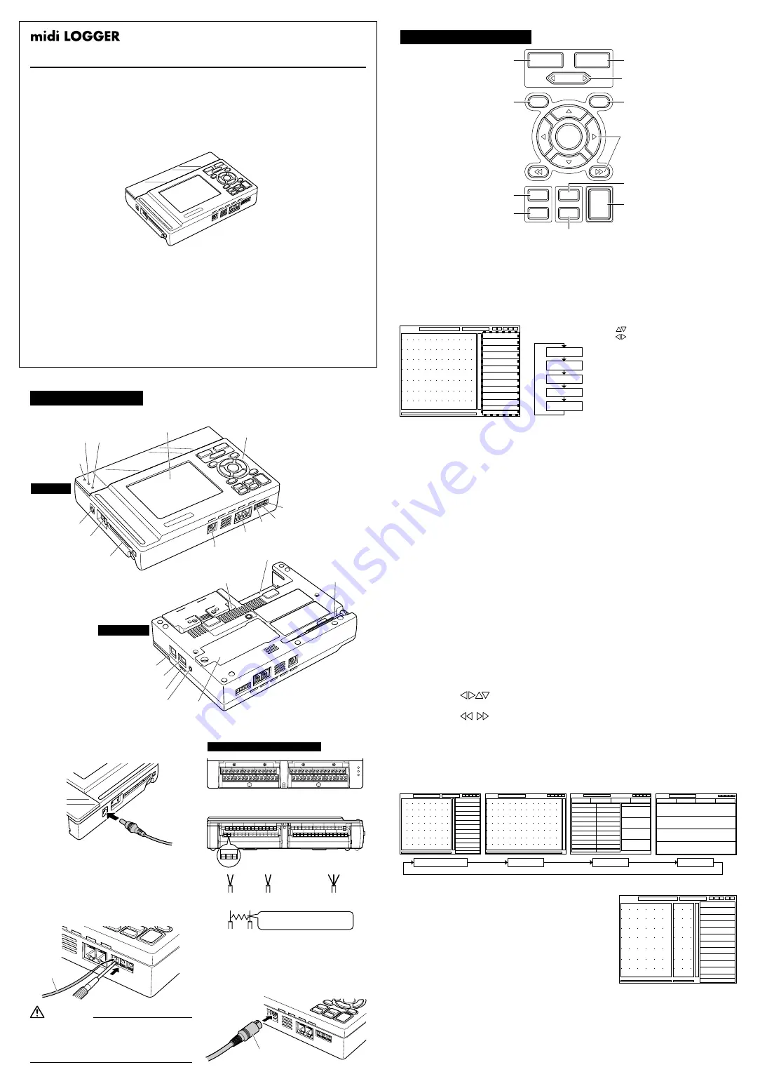
Part Names
Connecting the Logic Alarm Cable
Connect the round connector of the logic
alarm cable (B-513, option) to the logic
input /alarm output terminal on the GL450.
Connecting to an AC Power Supply
Connect the output side of the AC adapter
to the connector on the GL450.
Connecting the Grounding Cable
Using the screwdriver provided as a
standard accessory, press against the
button underneath the ground terminal
while connecting the grounding cable to
the GL450. Connect the other end of the
cable to ground.
Logic alarm cable (B-513)
Terminal layout on the top part of the unit
Input terminal unit 1
Input terminal unit 2
CH6
CH7
CH8
CH9
CH10
CH1
CH2
CH3
CH4
CH5
CH6
CH7
CH8
CH9
CH10
CH1
CH2
CH3
CH4
CH5
+ -
b
Terminal configuration
+ -
+
-
Voltage
+ -
Thermocouple
+ -
b
Resistance temperature
detector (RTD)
Current measurement
Signal
source
Amp Input Terminal Layout
CH GROUP
RANGE
/
SPAN
POSITION
TIME
/
DIV
QUIT
MENU
LOCAL
ENTER
DISPLAY
SAVE
REVIEW
START
STOP
CURSOR
(3) TIME/DIV key
(6) MENU key
(2) RANGE/SPAN/POSITION key
(5) QUIT key
(1) CH GROUP key
(8) DISPLAY key
(10) SAVE key
(4) START/STOP key
(9) REVIEW key
(7) Direction keys
(11) CURSOR key
(1) CH GROUP key
The [CH GROUP] key selects the channels in 10-channel groups. Press the key to move
to the next group of 10 channels. The number of channels varies according to the type of
input terminal unit installed.
GL450 Main Unit
Control Panel Keys
Grounding cable
Always connect the GND terminal and refer to
the safety precautions. The GL450 must be
grounded even when connected to other
devices and sharing a common ground level.
CAUTION
(2) RANGE/SPAN/POSITION key
These settings can be made or changed for each channel individually, even while the
GL450 is in the 'free running' status (not capturing data) or performing measurement.
(4) START/STOP key
Press the [START/STOP] key to select the START status (awaiting trigger). Press it once
again to select the STOP status (free running).
(8) DISPLAY key
Press the [DISPLAY] key to switch through the measurement modes.
(11) CURSOR key
When data is being replayed, press the [CURSOR] key to switch between Cursor A and
Cursor B.
(10) SAVE key
Press the [SAVE] key to save data, to make a copy of the screen, and to save the data
between cursors (only during a data replay operation).
(9) REVIEW key
If the [REVIEW] key is pressed during the Free Running
status (when data is not being captured), the captured
data is replayed.
If the [REVIEW] key is pressed during measurement,
past data is displayed together with the data currently
being measured in a dual-screen format.
(5) QUIT (LOCAL) key
Press this key to return the display to its former settings. It is also used to display
operations within a setting menu. (If the GL450 is in Remote status, press this key to
cancel the key lock status.)
(6) MENU key
Press the [MENU] key to switch through the detailed setting menus.
AMP (Amplifier settings): This menu is used to make the Input, Range, Filter settings, etc.
ANNO (Annotation settings): This menu is used to set and display comments for each channel.
DATA (Data settings): This menu is used to make the sampling interval and calculation settings.
ALM (Alarm settings): This menu is used to make the alarm and trigger settings.
FILE (File settings): This menu is used for PCMCIA card operations.
I/F (Interface settings): This menu is used to make the USB and TCP-IP settings.
OTHR (Other settings): This menu is used to make other settings such as the date/time
and display language settings.
INFO (Information): Device information is displayed on this screen.
(3) TIME/DIV key
Press the [TIME/DIV] key to switch through the waveform display speeds.
For current in the 4 to 20 mA range,
apply a resistance of 250 ohms and
perform measurement in the 1 - 5 V range.
JUL 19, 2005 1st edition
Monitor
Control panel keys
Power connector
Power LED
Data capture LED
Battery charging LED
Power switch
PCMCIA slot
Logic input/
Alarm output terminal
Synchronization connector terminal
GND
External trigger
Pulse input
Top panel
Input terminal 1
Input terminal 2
Screwdriver for mounting
the input terminal unit
USB connector terminal
LAN connector terminal
Monitor control dial
Battery
Humidity sensor connector
Bottom panel
• Use the [ ] keys to select the channel.
• Use the [ ] keys to change the setting.
MONITER
INPUT
RANGE
SPAN
POSITION
Displays digital values
Changes the input type: voltage, temperature or humidity
Changes the voltage and temperature ranges
Changes the waveform display range
Changes the waveform display position
Waveform
Wa Digital
Calculation
Digital
Dual-screen replay display
(7) Direction keys
Direction keys ( )
These keys move the cursor on the screen in the direction of the arrow.
Direction keys ( )
Press these keys to move the waveform displayed during a data replay operation. (If both
keys are held down simultaneously for three seconds or longer, the GL450 will enter key
lock status. To cancel the key lock status, hold down both keys for a further three seconds
or longer.)
CH1 -0.08mV
CH2 -0.00mV
CH7 +200.0C
CH10 +180.0C
1 -0.08mV
2 -0.00mV
3 -0.12mV
4 -0.2V
5 -0.012V
6 -134C
7 -0.3C
8 +35.8C
9 +12.5C
10 -0.08mV


