background image

308936

Rev. B

Supersedes Rev. A

First choice when

quality counts.

01944A

NOTE:

 Any modification of genuine Graco parts or replacement of parts with non-Graco parts will void agency approvals.

U.S. Patent No. 4,290,091; 4,219,865; 4,497,447; 4,462,061; 4,660,774; 5,063,350; 5,080,289; 5,289,977 
Patented 1986, 1987 Canada 
Brevete 1986, 1987 
U.K. Patent No. 2,147,158; 2,142,559B; 2,140,327–B 
Other U.S. and Foreign Patents Pending

UNICARB IS A REGISTERED TRADEMARK OF UNION CARBIDE, DANBURY CT.

INSTRUCTIONS-PARTS LIST

INSTRUCTIONS

This manual contains important
warnings and information.
READ AND KEEP FOR REFERENCE.
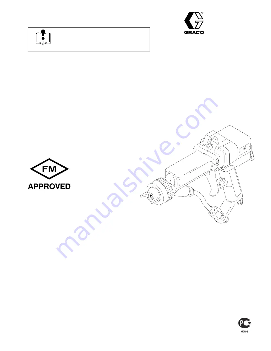
85 KV ELECTROSTATIC

Model PRO AA4500

/UNICARB

Air-Assisted Spray Gun

100 psi (7 bar, 0.7 MPa) Maximum Working Air Pressure
3000 psi (207 bar, 20.7 MPa) Maximum Working Fluid Pressure

For use with Class


I

, Group D paint  spray materials

Part No. 965722, Series B

Spray Gun with basic power supply, 
2-finger trigger

GRACO INC.

P.O. BOX 1441

MINNEAPOLIS, MN

55440–1441

COPYRIGHT 1999, GRACO INC.

Graco Inc. is registered to I.S. EN ISO 9001

Summary of Contents for UNICARB

Page 1: ...ding UNICARB IS A REGISTERED TRADEMARK OF UNION CARBIDE DANBURY CT INSTRUCTIONS PARTS LIST INSTRUCTIONS This manual contains important warnings and information READ AND KEEP FOR REFERENCE 85 KV ELECTROSTATIC Model PRO AA4500 UNICARB Air Assisted Spray Gun 100 psi 7 bar 0 7 MPa Maximum Working Air Pressure 3000 psi 207 bar 20 7 MPa Maximum Working Fluid Pressure For use with Class I Group D paint s...

Page 2: ...rotection Association NFPA 33 requirements use solvents with a flash point higher than 100 F 38 C or a solvent normally used in spray operations For European Countries complying with EN 50053 use solvents with a flash point as high as possible and higher than the ambient temperatures Use only non sparking tools to clean residue from the booth and hangers Do not flush the system with the gun electr...

Page 3: ...iately Permanently coupled hoses cannot be repaired replace the entire hose INSTRUCTIONS EQUIPMENT MISUSE HAZARD Equipment misuse can cause the equipment to rupture malfunction or start unexpectedly and result in a serious injury This equipment is for professional use only Read all the instruction manuals tags and labels before operating the equipment Use the equipment only for its intended purpos...

Page 4: ...eplacement 29 Electrode Replacement 30 Fluid Tube Removal Replacement 31 Fluid Filter Removal 31 Barrel Removal 32 Fluid Packing Adjustment 33 Fluid Needle Assembly Removal 34 Power Supply Removal and Replacement 35 Power Supply Adjustment 35 Turbine Alternator Removal and Replacement 36 Barrel Installation 36 ES ON OFF Valve Repair 37 Air Control Valve Repair 38 Air Valve Repair 39 Technical Data...

Page 5: ... needed to atomize higher solids materials The gun s internal power cartridge provides high voltage current The fluid is electrostatically charged as it passes the gun s electrode The charged fluid is attracted to the grounded object wrapping around and evenly coating all surfaces NOTE The gun s air control valve must be completely turned off to have airless atomization Closing the air control val...

Page 6: ...ories to order them Ventilate the Spray Booth WARNING FLAMMABLE OR TOXIC VAPOR HAZARD Provide fresh air ventilation to avoid the buildup of flammable or toxic vapors Do not operate the gun unless ventilation fans are operating Electrically interlock the gun air supply with the ventila tors to prevent gun operation without ventilating fans operating Check and follow all National State and Local cod...

Page 7: ...y See ACCESSORIES A B H K S R L N P Q M R WARNING SIGN W X Y Fluid Line Accessories Refer to Fig 1 1 Install a fluid filter S and drain valve R at the pump outlet Filtering the fluid will help remove coarse particles and sediment that could clog the spray tip WARNING INJECTION HAZARD The fluid drain valve R is required in your system to assist in relieving fluid pressure in the supply system hose ...

Page 8: ...wire to a true earth ground Check the electrical grounding of the gun as instructed on page 12 4 All air and fluid lines must be properly grounded Use only grounded hoses with a maximum of 500 feet 150 m combined hose length to ensure grounding continuity 5 All electric cables must be properly grounded 6 All persons entering the spray area their shoes must have conductive soles such as leather or ...

Page 9: ...t to interfere with the operator grounding through the gun ____ 7 The condition of the electrical components of the spray gun has been checked as instructed in Electrical Tests page 25 ____ 8 The ventilation fans are operating properly ____ 9 The workpiece hangers are clean and grounded Contact points must be sharp points or like knife edges ____ 10 All the debris including flammable liquids and r...

Page 10: ... the gun trigger safety latch 7 Trigger the gun into a grounded shrouded and vented metal waste container to relieve fluid and air pressure This may take several minutes 8 Lock the gun trigger safety latch again 9 Open the fluid drain valve required in system to help relieve fluid pressure In addition open the drain valve connected to the fluid pressure gauge in a system with fluid regulation to h...

Page 11: ...to prevent connecting another type of air supply hose to the gun air inlet and is available in lengths ranging from 6 to 100 feet 1 83 to 30 5 m See Accessories to order the hose A Connect the 1 4 npsm f left hand end of the Graco conductive air supply hose A to the gun air fitting 17 A Fig 2A 01989A 17 Left hand thread B Connect the other end of the air supply hose A to a filtered and regulated a...

Page 12: ...ir and fluid supply to the gun The fluid hose must not have any fluid in it D Make sure the air hose A is connected and the hose ground wire is connected to a true earth ground E Measure the resistance between the gun handle 7 and a true earth ground D a If using a black or grey air hose use a me gohmmeter E to measure the resistance Use an applied voltage of 500 minimum to 1000 volts maximum The ...

Page 13: ...vent that is compatible with the fluid to be sprayed using the lowest possible pressure 7 Follow the Pressure Relief Procedure WARNING INJECTION HAZARD To reduce the risk of a fluid injection injury always follow the Pressure Relief Procedure on page 10 before removing or installing the spray tip pre orifice air cap or tip guard 8 Select a spray tip The fluid output and pattern width depend on the...

Page 14: ...e pre orifice side facing down into the spray tip Fig 10E 8799A 9 9a 9b 11 Install the spray tip WARNING To reduce the risk of a serious injury including fluid injection follow the Pressure Relief Procedure on page 10 when you stop spraying and whenever you are instructed to relieve the pressure A Make sure there is no pressure in the system before removing or installing a spray tip Relieve the sy...

Page 15: ...ir Hose Length Recommended Air Hose Inlet Pressure 6 ft 1 8 m 40 psi 2 8 bar 15 ft 5 m 43 psi 3 0 bar 25 ft 8 m 45 psi 3 1 bar 36 ft 11 m 47 psi 3 2 bar 50 ft 15 m 50 psi 3 5 bar 75 ft 23 m 55 psi 3 8 bar 100 ft 30 5 m 60 psi 4 1 bar NOTE Using higher than recommended air pressures can reduce the life of the turbine alternator Lower pressures can be used but may reduce electrostatic wrap E Check t...

Page 16: ...atics Some objects with deep crevices or internal features may be painted more efficiently with the electrostatics turned off or in the LO setting see 15 below Be sure to turn off the electrostatics any time you are flushing the gun see page 18 NOTE When spraying the ES indicator light K will glow indicating the electrostatic charge 15 Use the ES HI LO lever 43g to change to either full voltage HI...

Page 17: ...recommended as a flush ing or cleaning solvent with this gun as it will damage nylon components Solvent left in gun passages could result in a poor quality paint finish and may draw current and reduce the elec trostatic effect Solvent in the power supply cavity can reduce the alternator life Do not use any cleaning meth od which may allow solvent into the gun air passages Do not point the gun up w...

Page 18: ...gun 1 Follow the Pressure Relief Procedure Warning on page 10 2 Make sure the ES ON OFF lever is turned to OFF and the trigger safety latch is locked before proceeding Fig 2 02002A ES OFF locked 3 Pointing the gun down unscrew and remove the retaining nut 8 tip guard 2 air cap 1 and fluid tip 9 You may have to turn the air cap with the tip guard to remove the air cap from the gun Set these parts a...

Page 19: ... from the gun 02341 02338 Fig 8 F A 9 Unlock the trigger safety latch and trig ger the gun into a grounded metal con tainer L to drain the fluid tube Fig 9 02006 L 10 Lock the trigger safety latch 11 Dip the end of a soft bristle brush into a compatible solvent Then point the gun down and clean the front with the brush and solvent 01948 02007 Fig 11 12 Dampen a soft cloth with solvent and wring ou...

Page 20: ...e gun air passages can cause poor atomization and excessive current demands and can damage the gun 16 Clean the retaining nut tip guard air cap and fluid tip with a soft brush daily minimum Clean the parts with a soft brush and replace them if they are damaged Be careful not to bend dam age or disengage the electrode wire Fig 16 02011 17 Wipe off the parts with a dry cloth Be careful not to bend t...

Page 21: ...tall the spray tip 9 and air cap 1 tip guard 2 and retaining nut 8 Tighten the retaining nut firmly CAUTION To avoid damaging the tip guard 2 orientate the air cap 1 before tightening the retaining nut 8 Do not turn the air cap when the retaining nut is tight 02088B 8 2 1 9 Fig 20 21 Hang up the gun until it is used again Fig 21 02012B CAUTION Always hang the gun with its nozzle pointing down to a...

Page 22: ...y The fluid pressure or fluid supply is insuf ficient There is air in the fluid supply line The CO2 percentage is fluctuating or is too high The fluid temperature is fluctuating Adjust the flluid CO2 supply system Check tighten the siphon hose connections bleed the air from the fluid line Check fluid CO2 supply system Check temperature control system Irregular pattern There is fluid buildup on the...

Page 23: ...ray tip or pre orifice See page 47 Remix or refilter fluid Use proper thinner Excessive spray fog Fluid thinned too much Properly thin fluid No fluid sprays from gun Fluid supply low Spray tip or pre orifice is dirty or clogged Spray tip damaged Fluid needle damaged Check Add fluid if necessary Clean spray tip and pre orifice See page 20 Check Replace spray tip See page 29 Replace fluid needle See...

Page 24: ... turbine inlet See page 15 Check gun resistance See page 25 Clean needle cavity Replace fluid needle See page 34 Be sure plug is in place on back of turbine alternator housing Remove and test turbine alternator See page 36 Check switch actuation replace if needed Operator gets shock Operator not properly grounded or is near an ungrounded object Gun not properly grounded Be sure floor is properly g...

Page 25: ...for use in a hazard ous area To reduce the risk of sparking do not use the megohmmeter to do the electrical tests unless The gun has been removed from the hazardous area Or all spraying devices in the hazardous area are turned off ventilation fans in the hazardous area are operating and there are no flammable vapors in the area such as open solvent con tainers or fumes from spraying Failure to fol...

Page 26: ...The resistance should be 297 to 363 megohms If the resistance is outside the specified range the power supply is defective and must be replaced If the resis tance of the power supply is correct proceed to the next test If you still have problems refer to Electrical Troubleshooting for other possible causes of poor performance or contact the nearest authorized service agency NOTE Be sure the seal 1...

Page 27: ...tal rod D still inside the barrel as shown in Fig 6 measure the resistance between the wire lead and the metal rod 3 If the resistance is still outside the specified range the gun barrel needs to be replaced If the resistance is correct install a new contact ring 3a and press it firmly into the groove on the front of the barrel Be sure the contact ring is in place before operat ing the gun WARNING...

Page 28: ...seals with petroleum jelly Do not over lubricate Only use genuine Graco parts Do not mix or use parts from other PRO Gun models Note that the air cap spray tip and tip guard for this gun are orange WARNING Some PRO AA4500 Gun replacement parts look similar to other PRO Gun parts but are not inter changeable When servicing do not mix or use other PRO Gun parts that may look similar but have differe...

Page 29: ... and never operate the gun without the contact ring in place Do not replace the contact ring with anything but a genuine Graco part 5 Trigger the gun and install the seat housing 21 with the 9 mm driver 64 Tighten the seat housing until it s snug and then tighten it 1 4 turn more CAUTION To avoid damaging the seat housing and gun barrel never over tighten the seat housing Over tightening may resul...

Page 30: ...e tip guard to remove the air cap from the gun 3 Pull the electrode 1a out of the backside of the air cap with a needle nose pliers 4 Push the new electrode through the air cap hole Place firm finger pressure on the electrode wire 1a on the backside of the air cap and make sure the short end BB of the electrode engages into the hole CC as shown in Fig 9 5 Assemble the spray tip air cap and tip gua...

Page 31: ...ube nut D threads 6 Install the fluid tube into the gun barrel by tighten ing the top fluid tube nut D hand tight then turn it 1 4 to 1 2 turn with a wrench There will be a gap between the nut and barrel Do not over tighten it 7 Make sure the fluid filter 14 is in place in the fluid fitting 10 Then tighten the bottom fluid tube nut C onto the fluid fitting make sure the top fluid tube nut D remain...

Page 32: ...racket that hold it in place Apply a low strength purple Loctite to setscrews before re installing them 3 Loosen the three cap screws 5 using the 4 mm driver 55 supplied 4 Hold the gun handle 7 with one hand and pull the barrel 3 straight away from the handle to remove it See Fig 13 CAUTION To avoid damaging the power supply 18 always pull the gun barrel straight away If necessary gently move the ...

Page 33: ... barrel as instructed on page 32 5 Place the 2 mm driver 58 supplied in the back of the fluid needle assembly Push the tool in and turn it clockwise slightly to tighten the packings See Fig 14 6 Assemble the barrel as instructed on page 36 7 Trigger the gun and install the seat housing 21 with the 9 mm driver 64 Tighten the seat housing until it s snug and then tighten it 1 8 turn more CAUTION To ...

Page 34: ...y CAUTION To avoid damaging the needle assembly be sure the needle is completely unthreaded before pushing it out of the barrel 8 Install the fluid needle assembly 28 into the gun barrel See Fig 15 Push in on the needle with the 2 mm driver 58 and tighten the assembly clock wise until just snug then 1 4 to 1 2 turn tighter 9 Install the trigger 13 and tighten the trigger screws 4 10 Assemble the b...

Page 35: ...y free from the gun handle 7 then pull it straight out 4 Inspect the power supply for any physical damage Check the electrical resistance as instructed on page 26 If needed replace the power supply Before installing the power supply inspect the seal 18e for any damage or swelling replace if neces sary Also make sure the gaskets pads 18a 18d are in place See Fig 16 5 Lubricate the o ring 37a and in...

Page 36: ... wire connector to the 3 prongs in the power supply Push the alternator 37 onto the power supply 18 until the retaining ring 35 engages with the alternator 7 Install the power supply in the gun handle as instructed on page 35 Barrel Installation 1 Be sure the gaskets 34 18a and spring 30 are in place See Fig 17 Replace if damaged 2 Place the barrel 3 over the power supply 18 and onto the gun handl...

Page 37: ...e lubricant on the o ring 36 can be pushed into the gun air pas sage and blemish the finish on the workpiece 6 Install the regulator disk 46 in the valve 38 with its bevelled side facing in toward the valve CAUTION Be sure the regulator disk 46 is installed correctly A missing or incorrectly installed regulator disc can cause severe damage to the turbine alternator 7 Install the valve 38 with the ...

Page 38: ... for wear or damage 7 Reassemble the air control valve 43 Lubricate the o rings 43e and the adjustment knob threads 43c with petroleum jelly Install the retaining ring 43h 8 Apply low strength purple Loctite or equivalent thread sealant to the threads of the valve housing 43d and install the air control valve assembly 43 into the gun handle To start the valve housing 43d threads into the handle tu...

Page 39: ... 41 23 for damage and replace if necessary Apply petroleum jelly to the o rings 6 Unscrew the packing nut 40 to check the u cup 42 Do not remove the u cup unless it is dam aged If the u cup 42 is removed be sure to install the air valve shaft 39 into the handle before installing the packing nut and u cup 7 Install the air valve shaft with the o ring 41 into the back of the gun handle 7 8 If remove...

Page 40: ...40 308936 Notes ...

Page 41: ...mark of the Loctite Corporation Noise levels measured with a 40 psi 2 8 bar air supply at the gun air inlet and typical gun air flow settings Noise levels measured with a 100 psi 7 bar air supply at the gun air inlet and maximum gun air flow settings Sound pressure was measured per Cagi Pneurop 1969 Sound power was measured per ISO 3744 1981 Radio Frequency Transmitter Approval for Gun Part No 236...

Page 42: ...34 35 36 37 37a 37b 38 39 40 41 42 43b 43d 43f 43g 43h 43e 43c 44 45 46 47 3a 9a 56 57 1a Item 1 includes item 1a Item 3 includes item 3a Item 18 includes items 18a to 18e Item 37 includes items 37a and 37b Item 43 includes items 43b to 43h Item 45 includes items 45a to 45e 01956D 9b 42 308936 Parts ...

Page 43: ... air valve cap PTFE 1 Ref No Part No Description Qty 24 110083 SET SCREW M4 x 0 7 1 26 186839 ES ON OFF LEVER 1 28 235798 FLUID NEEDLE ASSY 1 30 112691 SPRING compression 1 31 185079 PLUG 1 32 185119 SPACER ES valve 1 33 185112 FITTING barb 1 34 185113 GASKET manifold polyethylene 1 35 185114 RETAINER RING alternator 1 36 113746 O RING ES valve CV75 1 37 222319 TURBINE ALTERNATOR Includes items 37...

Page 44: ...9 15 ft 5 m 235070 25 ft 8 m 235071 36 ft 11 m 235072 50 ft 15 m 235073 75 ft 23 m 235074 100 ft 30 5 m Flexible Conductive Air Whip Hose 100 psi 7 bar 0 7 MPa Maximum Working Pressure Must be used with a full size Graco Conductive Air Supply Hose Metallic ground path 0 187 in 4 5 mm ID 1 4 npsm m left hand x 1 4 npsm f left hand 236130 3 ft 0 9 m 236131 6 ft 1 8 m Air Swivel Fitting 236129 100 ps...

Page 45: ...r fitting item 17 in parts list to provide an extended handle grip area Inline Fluid Filter 205265 60 mesh To replace the 100 mesh Filter 205264 that is included with the gun Electrode Replacement Kit 236001 Includes five electrodes Snap Ring Pliers 110090 For removing the ES ON OFF Valve Retaining Ring item 47 in parts list Brush 105749 For cleaning the gun Grease 217115 To grease the plastic ext...

Page 46: ...robe and Meter 236003 For direct measurement of gun output voltage Paint Resistance Meter 722886 Used with 722860 Paint Probe to measure resistance of paint Not for use in Hazardous areas Paint Probe 722860 Used with 722886 Paint Resistance Meter to measure resistance of paint Not for use in Hazardous areas Safety Warning Signs Available at no charge from Graco 180060 Warning Sign English 180061 W...

Page 47: ...00 GG3615 12 14 300 350 GG3217 4 6 100 150 0 017 0 432 GG3317 6 8 150 200 GG3417 8 10 200 250 GG3517 10 12 250 300 GG3617 12 14 300 350 Part No Fan Width at 10 in 260 mm in mm Orifice Size in mm GG3319 6 8 150 200 0 019 0 483 GG3419 8 10 200 250 GG3519 10 12 250 300 GG3619 12 14 300 350 GG3719 14 16 350 400 GG3421 8 10 200 250 0 021 0 533 GG3521 10 12 250 300 GG3621 12 14 300 350 GG3721 14 16 350 ...

Page 48: ...ion prepaid If inspection of the equipment does not disclose any defect in material or workmanship repairs will be made at a reasonable charge which charges may include the costs of parts labor and transportation DISCLAIMERS AND LIMITATIONS The terms of this warranty constitute purchaser s sole and exclusive remedy and are in lieu of any other warranties ex press or implied including warranty of m...

Reviews: