background image

OWNER’S MANUAL

308–021 Rev D

Supersedes C

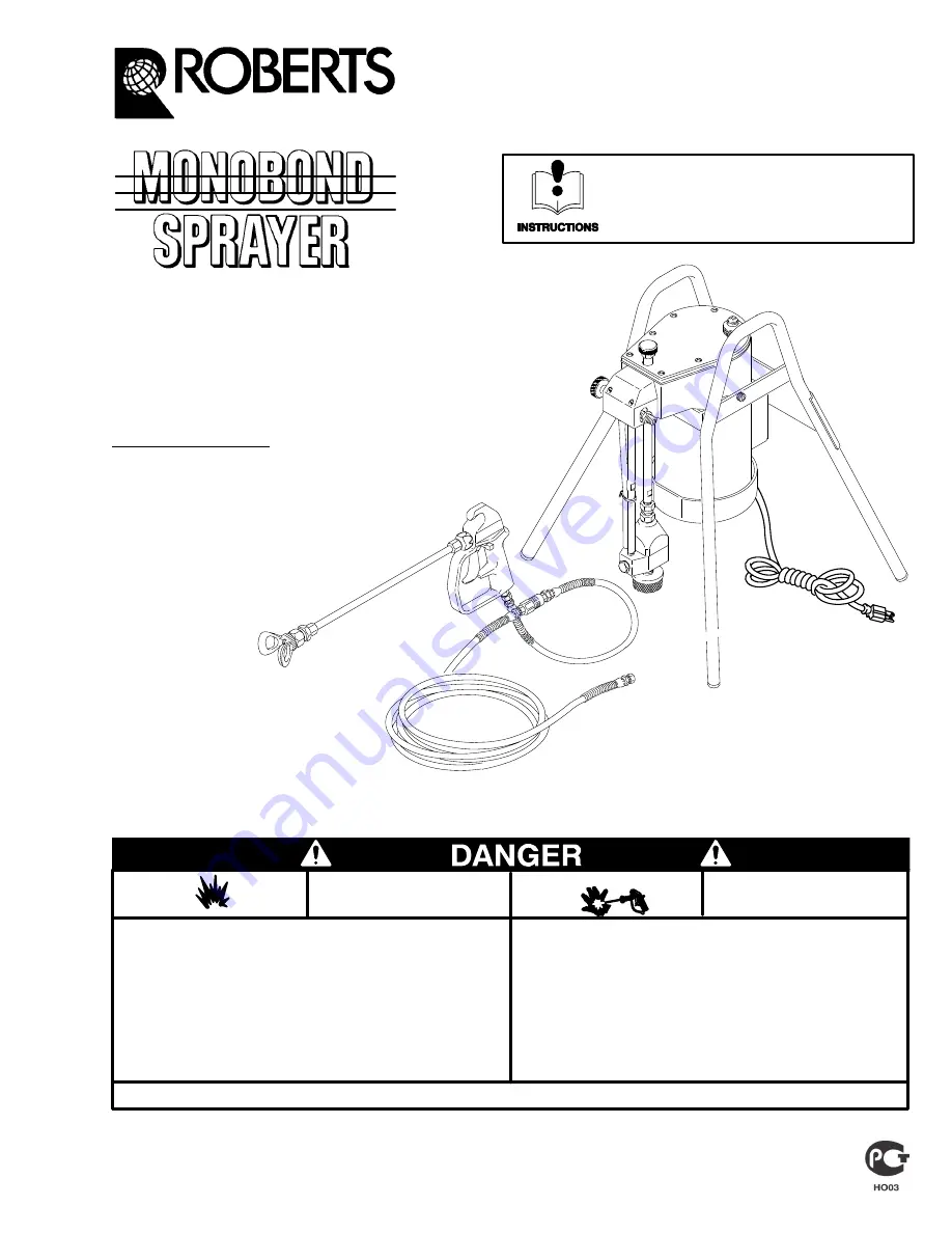
CARPET ADHESIVE SPRAYER

1/4 Gallon Per Minute, 120 VAC, 60 Hz

3000 psi (210 bar) Maximum Working Pressure

MODEL 61–251

For use with non–flammable,
water–base adhesive

Part No. 231–109, Series C

Complete Sprayer with hose and gun.

U.S. Patent No. 4,616,982 
U.K. Patent No. 2,165,591
Other Foreign Patents Pending

ROBERTS CONSOLIDATED INDUSTRIES,

INC.

P.O. BOX 1250/600 N. Baldwin Park Blvd.

City of Industry, California 91749

This manual contains important 
warnings and information. 
READ AND RETAIN FOR REFERENCE

Liquids can be injected into the body by  high pressure airless

spray or leaks – especially hose leaks.
Keep body clear of the nozzle. Never stop leaks with any part of the

body. Drain all pressure before removing parts. Avoid accidental

triggering of gun by always setting safety latch when not spraying.
Never spray without a tip guard.
In case of accidental skin injection, seek immediate “Surgical

Treatment”.
Failure to follow this warning can result in amputation or serious

injury.

FIRE AND

EXPLOSION HAZARD

SKIN INJECTION

HAZARD

READ AND UNDERSTAND ALL LABELS AND INSTRUCTION MANUALS BEFORE USE

Spray painting, flushing or cleaning equipment with flammable liq-

uids in confined areas can result in fire or explosion.
Use outdoors or in extremely well ventilated areas. Ground equip-

ment, hoses, containers and objects being sprayed.
Avoid all ignition sources such as static electricity from plastic

drop cloths, open flames such as pilot lights, hot objects such as

cigarettes, arcs from connecting or disconnecting power cords or

turning light switches on and off.
Failure to follow this warning can result in death or serious injury.

NOTE:

 This is an example of the DANGER label on your sprayer. This label

is available in other languages, free of charge. See page 15 to order.

Summary of Contents for 61-251

Page 1: ...tting safety latch when not spraying Never spray without a tip guard In case of accidental skin injection seek immediate Surgical Treatment Failure to follow this warning can result in amputation or serious injury FIRE AND EXPLOSION HAZARD SKIN INJECTION HAZARD READ AND UNDERSTAND ALL LABELS AND INSTRUCTION MANUALS BEFORE USE Spray painting flushing or cleaning equipment with flammable liq uids in...

Page 2: ...ty lever in the locked or inoperative position TRIGGER View from front of gun Diffuser The gun diffuser breaks up spray and reduces the risk of fluid injection when the tip is not installed Check diffuser operation regularly Follow the Pressure Relief Procedure below then remove the spray tip Aim the gun into a metal pail holding the gun firmly to the pail Using the lowest possible pressure trigge...

Page 3: ...ined hose length to ensure grounding continuity See Hose Grounding Continuity below 3 Spray gun obtain grounding through connection to a prop erly grounded fluid hose and sprayer 4 Object being sprayed according to local code 5 Fluid supply container according to local code 6 All solvent pails used when flushing according to local code Use only metal pails which are conductive Do not place the pai...

Page 4: ...raulic oil use only Graco Hydraulic Oil Part No 218 797 Install the fill cap See Fig 1 5 Check the electrical service It must be 120 VAC 60 Hz 15 Amp minimum Be sure the electrical out let is properly grounded You can use up to 100 foot 30 m of 3 wire 14 gauge minimum extension cord Longer exten sion cords may affect the sprayer performance Use more spray hose not longer extension cords Do not rem...

Page 5: ... pail of adhesive 5 Turn the sprayer ON and allow the adhesive to circu late through the bypass valve 4 for one or two min utes NOTE If the adhesive does not circulate back into the pail turn down the pressure and turn the motor on and off several times to help prime the sprayer 6 Turn the bypass valve 66 clockwise finger tight to close it this allows the pump to build up pressure 7 Release the tr...

Page 6: ...rs thereafter about weekly Check or change the hydrau lic oil 1 Check the oil after each use of the sprayer 2 Change the oil after the first 20 hours of operation 3 Change the oil each 50 hours thereafter about twice monthly Replace the diaphragm After every 500 gallons of fluid sprayed 4 to 6 months Tighten the Fluid Pump Screws and Inlet Valve See Fig 5 1 Follow the Pressure Relief Procedure on ...

Page 7: ...r to drain the adhesive Now turn off the sprayer See Fig 8 2 Place the fluid pump in a grounded pail of solvent 3 Check to be sure the trigger safety lever is locked Remove the spray tip from the gun Unlock the safety lever Hold a metal part of the gun firmly to the side of a grounded metal pail Close the bypass valve Trigger the gun into the pail T urn on the sprayer Watch the side of the pail fo...

Page 8: ...ween needle and diffuser Disassemble and clean gun Spray gun leaks Worn seal or loose fluid fitting Repair gun order Kit no 218 588 tighten fluid fitting Spray gun won t spray or low output from gun Fluid supply empty Refill and reprime system Spray tip clogged Use Reverse A Clean feature to clear tip clog see page 12 Gun filter if used is clogged Clean or replace Sprayer will not start Sprayer no...

Page 9: ...p Replace Sprayer sucks fluid builds pressure but pressure drops when gun is trig No spray tip on gun Shut off sprayer and install tip but pressure drops when gun is trig gered Spray tip orifice too large for the fluid or worn tip Try a smaller tip or a new tip Inlet screen clogged Clean Optional gun filter clogged Clean or replace Optional gun filter screen too fine for type of fluid Install larg...

Page 10: ...e will cause performance problems 6 Install the housing 28b and torque to 125 150 in lb 14 17 N m 7 The last coil on one end of the spring is turned in Place this end over the stud in the plug 28d Install the ball 28e washer 28f and plug and torque to plug to 380 300 in lb 32 34 N m Pressure Control See Fig 10 When removing the pressure control 4 to check or clean it always replace the seal 4a Whe...

Page 11: ...n it on Run the sprayer for two minutes to fill the hydraulic sys tem Increase the pressure to maximum and turn the sprayer on and off four times to help rid the hydraulic system of air Fig 10 21 22a 22b 26a 26 27 25 24 28d 28f 28c 28e 28b 28a C 4 4a 38 37 36 66 35 3 67 20 28 18a 0284 1 3 4 2 Torque to 125 150 in lb 14 17 N m Apply sealant to the threads Lubricate the internal threads Torque to 12...

Page 12: ... 4 2 Lubricate the threads Torque to 40 45 in lb 54 60 N m Torque to 130 140 in lb 15 16 N m Apply tape to the top and bottom threads See Detail A page 14 Torque to 70 90 in lb 8 10 N m The tube must drop freely in the pipe 1 Apply sealant to the threads The seal in the bearing must face down Apply threads sealant to the motor tie bolts See Detail B on page 14 5 7 8 6 10 3 2 5 7 8 6 10 1 4 83 9 9 ...

Page 13: ...G cylinder 1 42 183 840 CYLINDER pump 1 43 108 153 FITTING hose barbed 1 44 107 511 SPRING compression 1 45 180 479 PISTON 1 46 180 480 WASHER spring 1 47 107 517 RING retaining external 1 48 107 524 RING retaining external 1 49 107 513 KEY woodruff 1 50 218 909 ECCENTRIC ASSEMBLY 1 52 108 042 SCREW cross head recessed M4 x 14 0 8 53 180 650 GASKET housing 1 54 107 518 BEARING ball 1 55 107 519 SE...

Page 14: ...G compression 1 28d 218 505 PLUG ball stop 1 28e 112 618 BALL carbide 1 28f 180 454 WASHER 1 68 186 334 ADAPTER tip 1 93 166 969 WASHER 1 94 110 761 TIP spray 16 fan 0 031 orifice 1 96 220 251 TIP GUARD Includes washer item 93 1 98 223 541 HOSE coupled 1 4 x 50 1 99 204 940 SWIVEL straight 1 100 214 701 HOSE coupled 3 16 x 3 1 101 222 002 GUN Basic see 307 821 for parts 1 102 218 245 TUBE extensio...

Page 15: ...A for the best visiblity Order the labels directly from your Graco distributor without charge Call 1 800 328 0211 A Manual Change Summary Assembly Changed Part Status Ref No Part No Part Name Model 61 251 Sprayer Old New Old New Delete Delete Add Add 27 27 28 28 28c 28e 28c 28e 108 143 218 798 218 732 236 954 107 521 101 701 112 619 112 618 Strainer Strainer Outlet valve Outlet valve Spring Ball S...

Page 16: ... non Graco component parts Nor shall Graco be liable for malfunction damage or wear caused by the incompatibility with Graco equipment of structures accessories equipment or materials not supplied by Graco or the improper design manufacture instal lation operation or maintenance of structures accessories equipment or materials not supplied by Graco This warranty is conditioned upon the prepaid ret...

Reviews: