background image

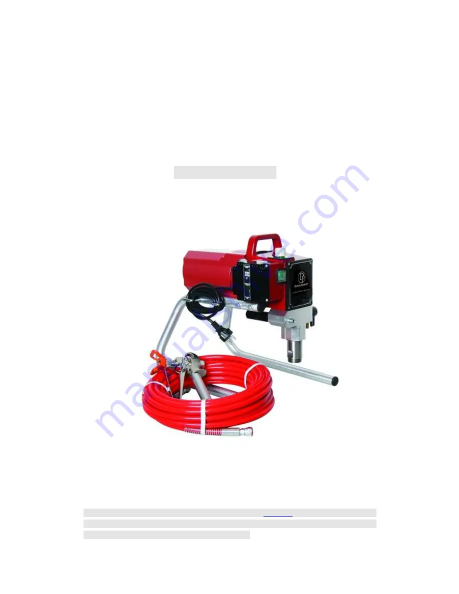
Operation manual for 

Airless paint 

sprayer


High Pressure Electric 

Airless paint sprayer Titan 440i

 model


intelligent    series   


Remark

:  this  guide  manual  is  the  same  with  model 

DP-6389

  ,the  content  include  :the 

operation of equipment,cleaning ,maintenance ,and repair,be sure to pre-operational ,read 

the manual carefully before you use this machine.                                             


Summary of Contents for Titan 440i

Page 1: ...less paint sprayer Titan 440i model intelligent series Remark this guide manual is the same with model DP 6389 the content include the operation of equipment cleaning maintenance and repair be sure to pre operational read the manual carefully before you use this machine ...

Page 2: ...mediately The maximum operating range of the sprayer is 3200 PSI 221BAR fluid pressure PREVENTION NEVER aim the airless spray gun at any part of the body NEVER allow any part of the body to touch the fluid stream DO NOT allow body to touch a leak in the fluid hose NEVER put hand in front of the gun Gloves will not provide protection against an injection injury ALWAYS lock gun trigger shut pump off...

Page 3: ...ounded to prevent static sparks Use only conductive or grounded high pressure fluid hose Gun must be grounded through hose connections Power cord must be connected to a grounded circuit Always flush unit into separate metal container at low pump pressure with spray tip removed Hold gun firmly against side of container to ground container and prevent static sparks Follow material and solvent manufa...

Page 4: ... of couplings Immediately replace hose if any of those conditions exist Never repair a paint hose Replace with a grounded high pressure hose All hoses swivels guns and accessories must be pressure rated at or above 3200PSI 221 BAR Do not spray outdoors on windy days Wear clothing to keep paint off skin and hair Always unplug cord from outlet before working on equipment Grounding Instructions This ...

Page 5: ... will cause a drop in line voltage resulting in loss of power and overheating 2 Name of equipment Components and features introduction A Motor DC motor 220V 50HZ single phase B ICS intelligent Pressure controller Pressure sensors and equipment have suggested that the status of the equipment fuction C Suction Components Use Within the upper and lower Components for the two valve coating will be add...

Page 6: ...Link Coating tube and manometer Position I Suction tube Will be from buckets in the paint inhalation equipment J Paint return tube Return to the state paint or solvent outflow from here The pressure control button operating Constructions Nopressurearea yello w indicate that close state Middle pressure area green indicate that middle pressure High pressure red indicate that high pressure pressure c...

Page 7: ...ightly firstly contect on the coating manometer exit then 15 meter high presure nylon coating of pressure gauges connected to the export terminal and screwed tightly pressure gauge in the first coating to the exit havig to use two wrench will be no high pressure airless spray gun connected to the head and another screwed tightly detemine pressure manometer control buttons set in the display more t...

Page 8: ... been good and have been initially harmonic filtering otherwise undesirable coating equipment will in creas wear and reduce the life span of equipment in addition each time before spraying the paint must be used by delicated diluent such as spraying latex paint water can be used to allow equipment to cycle again and again spraying the following is operation steps add suction tube will be fitted wi...

Page 9: ...t in the middle yellow area but the bottom of the location of equipment functioning return valve will be installed in the vertical position start equipment equipment to begin operation until the outflow of the paint from the reflux tube shut close equipment power move the reflux tube to the coating buckets return valve will be set in the horizontal position Turn on the power switch open spray gun ...

Page 10: ...raying check compliance with electricity Before each spraying we must add seal oil into the mouth drop PSL 5 6 after each spraying the equipment must be thoroughly cleaned and parts after each spraying pleas high pressure hose coiled to prevent damage to tie If long term storage does not work should be used to protect the body fluid blue bottle a bottle of protection against the bucket of water to...

Page 11: ... gun not proper button up to move a trigger with index finger and middle finger too tightly 3 Each spray gun should be in the process of moving and dynamic relaxation trigger deduction so the workpiece surface can be avoided excessive accumulation of paint flow and the formation of pegging as for chart 4 Spray gun should be vertical with the workpiece surface the surface from 25 to 30 cm distance ...

Page 12: ...t of the lap so the entire work surface coating line Uniform as for chart 6 Before Members of the spraying operation to find the best in the vicinity of wood or non construction of a workpiece on the test spraying spraying to adjust the distance and spray pressure as shown below the correct spraying distance and the pressure to achieve perfection Spraying effect ...

Page 13: ...trigger makes solvents or clear water flush to remain coating inside high pressure tube and spray gun until solvents or clear water are jet from the muzzl shut spray gun insurance as the right chart Loaded nozzle jacket and open spray gun insurance Nozzle will be reversed 180 degrees sustained gun deduction 1 2 seconds cleaning nozzles nozzles and nozzle jacket unloaded and cleaned with brushes cl...

Page 14: ... replacement steps pump filter Using the wrench will pump a body filter outer shell to unload Clockwise direction to revolving pump filter slightly Carefully checked filter a net and seal ring completely when it s necessary Carry on cleaning or replacement Anti clockwise direction to replace or clean the filter Installed to filter screwed tightly onto the out shell gun body filter Open spray gun i...

Page 15: ... out from the below cylinder when drawing Out the equipment will be slightly tilted to the future operation more convenient Ball Valve repair steps all the components in the equipment ball valves are the most vulnerable to not clean and cleaning equipment can not be plugged so that the normal operation sitting position so the ball valve cleaning and maintenance is very important the following is t...

Page 16: ...locator removed Will be removed within the shell on the three ring Cleaning suction components shell will be installed with new white ring back Shell Installation of the order and direction of making reference to the following diagram Note new suction equipment manufactured components for the black ring and suction component repair packet ring is white 上部密封圈安装方向 下部密封圈安装方向 O 型密封圈在安装时应将上部 O 型密封圈在安装时...

Page 17: ... shell Suction pipe will be installed under the block and back with a fixed clasp Will be return tube back to the installation of suction screwed tightly onto the components According to the operation steps to activate the equipment and inspection equipment availability drip 21 According to the operation steps to activate the equipment and inspection equipment availability drip Note Even if there ...

Page 18: ...wear 6 ball valve seat replacement Equipment is impossible to maintain pressure 7 Return valve wear 7 Return valve replacement 1 set Return valve too low 1 increase pressure 2 Filter plug 2 Cleaning or replacement filters Pressure shortage 3 nozzle Excessive or wear 3 Replacement nozzles 1 Incorrect paint coating pipe 1 Replacement of the right paint pipe 2 nozzle too much or wear 2 Replacement no...

Page 19: ...and equipment seal ring 4 Paint high viscosity 4 Reduce the viscosity of paint Trailing spray sites are phenomena 5 nozzle Wear 5 Replacement nozzles Uneven spray sites 1 Nozzle clogging or wear 1 Replacement nozzles Middle thick 1 there are gaps for Nozzle 1 Replacement nozzles Spray rate distortions side 1 Nozzle clogging or wear 1 Replacing or cleaning nozzle 1 Suction tube leakage 1 check and ...

Page 20: ...20 8 exploded drawing and parts list Suction component decomposition map ...

Page 21: ...21 ...

Page 22: ... Screw 2 31 Return valve casing 2 9 Lower seal ring 2 32 O type seal ring fluoroelastomers 2 10 Plunger rod 1 O type seal ring Teflon 1 11 the upper ball valve seal ring 1 33 return valve pole 1 12 Cover the ball on the ball valve 1 34 Return valve spring 1 13 the upper ball valves steel Ball 1 35 Return valve fixed nut 1 14 the upper Ball Valve ball on the Block 1 36 Return valve switch Block 1 1...

Page 23: ... would recommend that you use a wide spray and the rate of flow to the larger atomizing nozzle coatings in the table below is different coating viscosity we recommended by the nozzle aperture size notice Do not use more than the support of equipment nozzle diameter Nozzle diameter inches spray paint head of Fliter 011 013 Low Viscosity Varnish or color paint 100 head red 015 019 Oil and latex pain...

Page 24: ...240V Output voltage DC200 220V frequency 50HZ Maximun output pressure 20MPa The largest unloading flow 2 1L min The largest spray flow 1 9L min Effective spray distance 350 400mm Spray width 250mm Compressive strength of the high pressure 30 MPa Max nozzle type 515 519 N W 18 5KG ...

Page 25: ...t failures and electrical parts thereof and other non normal wear and tear Free for the maintenance of the above including labour costs and replacement costs and must produce proof of the purchases and effective products that specific date of purchase and exclusive pre code or no warranty 5 are not covered by warranty consumable products including all the seals ring gaskets nozzles needle guns var...

Reviews: