background image

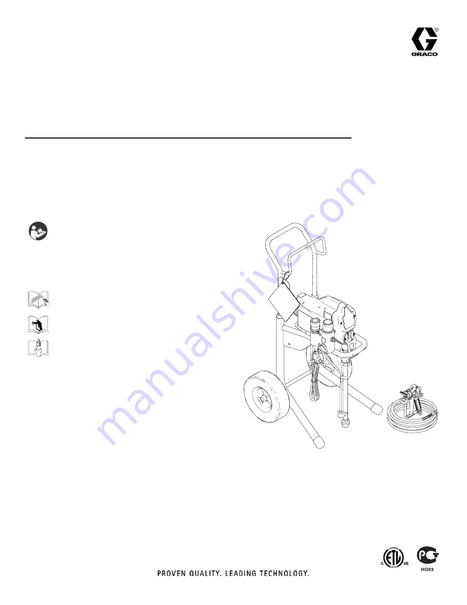
For portable spray application of architectural paints and coatings -

190

ES

 Model: 261825

210

ES

 Model: 261830

Maximum Working Pressure: 3000 psi (20.7 MPa, 207 bar) 

Important Safety Instructions

Read all warnings and instructions in this 
manual. Save these instructions.

Related Manuals

311988

312830

English

312831

Français

312832

Español

312015

ti16975a

311990F

Repair

190

ES

/210

ES


Electric Airless Sprayer

US Patent No. D580,518,S

ENG

Summary of Contents for 190ES 261825

Page 1: ...um Working Pressure 3000 psi 20 7 MPa 207 bar Important Safety Instructions Read all warnings and instructions in this manual Save these instructions Related Manuals 311988 312830 English 312831 Français 312832 Español 312015 ti16975a 311990F Repair 190ES 210ES Electric Airless Sprayer US Patent No D580 518 S ENG ...

Page 2: ...ts on or off when flammable fumes are present Ground equipment and conductive objects in work area Read Grounding instructions If there is static sparking or you feel a shock stop operation immediately Do not use equipment until you identify and correct the problem Keep a working fire extinguisher in the work area ELECTRIC SHOCK HAZARD Improper grounding setup or usage of the system can cause elec...

Page 3: ...vents in pressurized aluminum equipment Such use can cause serious chemical reaction and equipment rupture and result in death serious injury and property damage BURN HAZARD Equipment surfaces can become very hot during operation To avoid severe burns do not touch hot equipment Wait until equipment has cooled completely MOVING PARTS HAZARD Moving parts can pinch or amputate fingers and other body ...

Page 4: ... W X Ref Component A Pressure Control B ON OFF Switch D Power Cord E Fluid Outlet F Prime Valve G Kick Stand 210ES Series A H Pump J Suction Tube K Drain Hose M Fluid Hose N Gun P Tip R Guard S Trigger Safety Lock T Serial Number ID Label U Filter Cap V Pail Hook W Power Flush Adapter X Shutoff Valve ...

Page 5: ...through connection to a properly grounded fluid hose and pump Fluid supply container follow local code Solvent and Oil based fluids follow local code Use only conductive metal pails placed on a grounded sur face such as concrete Do not place the pail on a non conductive surface such as paper or cardboard which interrupts grounding continuity Grounding the metal pail connect a ground wire to the pa...

Page 6: ... 2 Hold gun against side of grounded metal flushing pail Trigger gun to relieve pressure 3 Turn prime valve down If you suspect the spray tip or hose is clogged or that pressure has not been fully relieved after following the steps above VERY SLOWLY loosen tip guard retaining nut or hose end coupling to relieve pressure gradually then loosen completely Clear hose or tip obstruction 4 Engage trigge...

Page 7: ...d on hot bare motor could cause fire or explosion To reduce risk of burns fire or explosion do not operate sprayer with cover removed To reduce risk of serious injury including electric shock Do not touch moving or electric parts with fingers or tools while testing repair Unplug sprayer when power is not required for testing Install all covers gaskets screws and washers before you operate sprayer ...

Page 8: ...chanical 1 Pump frozen or hardened paint Thaw sprayer if water or water based paint has frozen in sprayer Place sprayer in warm area to thaw Do not start sprayer until thawed com pletely If paint hardened dried in sprayer replace pump packings See page 12 Dis placement Pump Replacement 2 Displacement pump connecting rod pin Pin must be completely pushed into connecting rod and retaining spring mus...

Page 9: ...inals Securely recon nect leads 6 Motor thermal switch Yellow motor leads must have continuity through thermal switch Replace motor See page 26 Motor Replace ment 7 Brush cap missing or loose brush lead connections Install brush cap or replace brushes if leads are damaged See page 17 Motor Brush Replacement 8 Brush length which must be greater than 1 4 in 6mm NOTE Brushes do not wear at the same r...

Page 10: ...d Electric Requirements 7 Leads from motor to circuit board for damaged or loose wire con nectors Inspect wiring insulation and terminals for signs of over heating Be sure male terminal pins are centered and firmly connected to female terminals Replace any loose terminals or damaged wiring Securely reconnect terminals 8 Worn motor brushes which must be greater than 1 4 in 6 mm Replace brushes See ...

Page 11: ...acement 2 Connecting rod assembly for damage Replace connecting rod assembly See page 12 Displacement Pump Replacement 3 Gears or drive housing Inspect drive housing assembly and gears for damage and replace if necessary See page 14 Drive Housing Replacement Motor is hot and runs intermittently 1 Be sure ambient temperature where sprayer is located is not more than 115 F 46 C and sprayer is not lo...

Page 12: ...Loosen two screws 11 and remove pail hanger 10 3 Loosen nut 37 and remove suction tube 39 Loosen nut B and remove coupled hose 42 4 Cycle pump until pin 31 is in position to be removed 5 Disconnect power cord from outlet 6 Push up retaining spring C Push out pump pin 31 7 Loosen pump jam nut 34 Unscrew and remove pump 33 11 10 ti9138a 42 B 37 39 ti9139a C 31 ti9040a 34 33 ti9141a ...

Page 13: ... until nut stops Tighten jam nut by hand then tap 1 8 to 1 4 turn with a 20 oz maximum hammer to approximately 75 ft lb 102 N m 8 Install suction tube 39 and coupled hose 42 Tighten nuts 37 and B 9 Fill packing nut with Graco TSL until fluid flows onto top of seal Install pail hanger 10 with screws 11 If pump pin works loose parts could break off due to force of pumping action Parts could project ...

Page 14: ...a liberal coat of grease to gears and needle bearing surfaces Install thrust bearing 28 and gears 26 and 27 in motor front endbell 2 Push drive housing 29 into motor front endbell Insert gear crank 27 through hole in connecting rod 30 3 Install four screws 4 and screw 13 4 Install cover 32 with two screws 11 5 Install pump 33 Displacement Pump Replace ment page 12 CAUTION Do not drop gear cluster ...

Page 15: ... there are no electrical shorts If motor does not spin freely armature is shorted Replace motor page 26 Armature Brushes and Motor Wiring Open Circuit Test Continuity 1 Connect red and black motor leads with test lead Turn motor fan by hand at about two revolutions per second 2 If uneven or no resistance check for missing brush caps broken brush springs brush leads and worn brushes Repair as neede...

Page 16: ...11 and front cover 32 5 Remove screw 13 and shroud 12 6 Remove retaining ring 57b on back of motor 7 Pull off fan 57a Installation 1 Slide new fan 57a on back of motor Be sure fan blades face motor 2 Install spring clip 57b 3 Install shroud 12 with screw 13 4 Install front cover 32 with two screws 11 5 Install toolbox 3 with two screws 5 190ES 210ES Series A 6 Install kick stand 66 210ES Series A ...

Page 17: ...r Install positive red brush lead in top of motor and negative black brush lead in side of motor 2 Push each cap A into place over brush Orient each cap with the two projections on either side of the brush lead You will hear a snap when cap is securely in place 3 Strip approximately 1 4 inch 6 mm of insulation from end of each yellow wire C from motor 4 Insert stripped end into end of a butt splic...

Page 18: ... from control board 18 6 Disconnect motor connector D from control board 18 7 Remove three screws 11 securing control board to housing two are located on the front and one on the back next to the power cord 8 Pull control board out slightly and then slide control board back and off of frame 9 Remove grommet and wires from strain relief 10 Remove two power cord C connectors from control board 120V ...

Page 19: ... to 30 35 in lb 3 4 3 9 N m 5 Connect motor connector D and pressure control assembly connector A 6 Install shroud 12 with screw 13 Install front cover 32 with two screws 11 see illustration page 15 7 Install toolbox 3 with two screws 5 190ES 210ES Series A 8 Install kick stand 66 210ES Series A Route power cord 19 between coupled hose 42 to filter manifold and sprayer frame ti6122a 18 Grommet Str...

Page 20: ... kick stand 66 210ES Series A 3 Remove two screws 5 and toolbox 3 190ES 210ES Series A 4 Remove two screws 11 and front cover 32 Remove screw 13 and shroud 12 see illustra tion page15 5 Remove fuse from control board Installation 1 Install Fuse 119277 on control board 2 Install shroud 12 with screw 13 Install front cover 32 with two screws 11 see illustration page 15 3 Install toolbox 3 with two s...

Page 21: ...over 32 5 Remove screw 13 and shroud 12 6 Disconnect pressure switch connector A from con trol board 18 Pull bushing 23 from hole K 7 Pull wires through hole K 8 Turn pressure control knob 17 counter clockwise as far as you can to access flats on either side of pressure control 9 Loosen and unscrew pressure control 10 Remove pressure control 11 13 12 32 ti9130a 18 A K 23 ti9129a Caution If you pla...

Page 22: ... Tuck wires into pressure control wire cap 21 and route wires toward cap opening Feed wires through housing hole K 6 Insert bushing 23 in hole K 7 Connect pressure switch connector A to control board 18 8 Install shroud 12 with screw 13 Install front cover 32 with two screws 11 see illustration page 15 9 Install toolbox 3 with two screws 5 190ES 210ES Series A 10 Install kick stand 66 210ES Series...

Page 23: ...ld 43 5 Remove valve seat 44b and seat gasket 44a from inside of filter manifold or end of drain valve Installation 1 Install new seat gasket 44a and valve seat 44b on end of drain valve 2 Screw drain valve 44 into filter manifold 43 Torque to 120 to 130 in lb 3 Push valve base 45 over drain valve 44 and then valve drain handle 46 over valve base 4 Install pin 47 in drain valve handle If necessary...

Page 24: ...rbed fitting 51 into filter manifold 43 2 Push drain line 49 onto barbed fitting To reuse existing barbed fitting 51 and drain line 49 cut and remove remaining drain line material from end of barbed fitting To make drain line more pliable and easier to install over barbed fitting heat end of drain line 49 with a hair dryer or place end in hot water a few seconds 51 49 ti9156a 43 ...

Page 25: ...ent Removal page 18 2 Remove green ground screw 20 and disconnect green ground wire G from frame Installation 1 Connect green ground wire G to frame with green ground screw 20 Be sure green ground wire ter minal faces up or wires could get caught in shroud 2 Install control board Control Board Replacement Installation page 19 G 20 ti9137a ...

Page 26: ...nstallation 1 Install cover 14 on motor 57 Install motor on frame 1 with four screws 4 2 Connect green ground wire G to frame with green ground screw 20 Be sure green ground wire ter minal faces up or wires could get caught in shroud See illustration page 25 3 Install manifold 43 with two screws 4 4 Install control board Control Board Replacement page 18 5 Install drive housing Drive Housing Repla...

Page 27: ...120V Wiring Diagram 311990F 27 120V Wiring Diagram Red Black Pressure Control Assembly Power Plug White Green Black from Motor 2 x Yellow ON OFF Switch ti5643a Capacitor Replaceable Fuse ti5643 ...

Page 28: ...Parts 28 311990F Parts 13 4 29 28 27 26 57 14 1 4 42 30 2 12 40 41 39 38 37 36 32 11 11 10 31 34 33 35 64b 65 63b 68 64a 63a 30a 15 16 57a 57b 69 70 89 93 ti9157a ...

Page 29: ...ght 1 32 15E630 COVER front 1 33 255198 PUMP displacement includes 35 Manual 312015 1 34 195150 NUT jam pump 1 35 162453 FITTING 1 4 npsm x 1 4 npt 2 36 235004 STRAINER 3 4 16 unf 1 37 15E813 NUT jam 1 38 15B652 WASHER suction 1 39 15J801 TUBE suction intake 1 40 103413 O RING 1 41 115099 WASHER garden hose 1 42 15J744 HOSE cpld 1 57 MOTOR electric 120V 255157 190 ES includes 57a 57b 1 249040 210 ...

Page 30: ...BUSHING universal 1 43 15J745 MANIFOLD Filter 190ES 210ES 1 44 235014 VALVE drain includes 44a 44b 1 44a 111699 GASKET seat 1 44b 187615 SEAT valve 1 45 224807 BASE valve 1 46 187625 HANDLE valve drain 1 47 111600 PIN grooved 1 48 195811 LABEL instruction 1 49 15K092 TUBE drain 1 50 244035 DEFLECTOR barbed 1 51 M70809 FITTING barbed hose 1 52 104361 O RING 1 53 243080 FILTER fluid 1 54 15E288 INSE...

Page 31: ... Graco such as electric motors switches hose etc are subject to the warranty if any of their manufacturer Graco will provide purchaser with reasonable assistance in making any claim for breach of these warranties In no event will Graco be liable for indirect incidental special or consequential damages resulting from Graco supplying equipment hereunder or the furnishing performance or use of any pr...

Page 32: ...test product information available at the time of publication Graco reserves the right to make changes at any time without notice Original instructions This manual contains English MM 311990 Graco Headquarters Minneapolis International Offices Belgium Korea China Japan GRACO INC P O BOX 1441 MINNEAPOLIS MN 55440 1441 Copyright 2010 Graco Inc is registered to ISO 9001 http www graco com Rev 03 2011...

Reviews: