GEA HGX12P CO2, Assembly Instructions Manual
The GEA HGX12P CO2 comes with a comprehensive Assembly Instructions Manual for hassle-free installation. This manual is available for free download from our website, enabling you to easily access the necessary guidance for assembling your product. Ensure a smooth setup process and maximize your experience with the GEA HGX12P CO2. (Note: Download the manual for free at manualshive.com).
Share
Download


Reviews:
No comments
Related manuals for HGX12P CO2

VRJ
Brand: Danfoss Pages: 24
MOBILAIR M27
Brand: KAESER KOMPRESSOREN Pages: 304

SEH004700
Brand: Super Ego Pages: 8

71-075
Brand: AirMan Pages: 80

ADLER /BARBOUR SERIES
Brand: Waeco Pages: 32

AO620/0414
Brand: Rockworth Pages: 3

007341
Brand: Meec tools Pages: 36

Copeland ZR16
Brand: Emerson Pages: 22

ZP14
Brand: Emerson Pages: 25

Copeland YF05K1E
Brand: Emerson Pages: 38
COPELAND ZH04K1P
Brand: Emerson Pages: 39

Copeland YRH KTE Series
Brand: Emerson Pages: 34

VSG & VSSG
Brand: Emerson Pages: 86
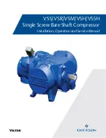
Vilter VSH
Brand: Emerson Pages: 206

VSG
Brand: Emerson Pages: 100
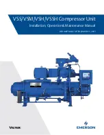
Vilter VSH
Brand: Emerson Pages: 250

IRONFORCFe WL6500 series
Brand: Campbell Hausfeld Pages: 24

RD-AC08
Brand: Raider Pages: 74


