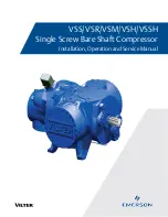
background image

VSS/VSR/VSM/VSH/VSSH

Installation, Operation and Service Manual

Single Screw Bare Shaft Compressor

Summary of Contents for Vilter VSH

Page 1: ...VSS VSR VSM VSH VSSH Installation Operation and Service Manual Single Screw Bare Shaft Compressor ...

Page 2: ......

Page 3: ...ing and maintaining the system to prevent conditions that could lead to liquid carry over Vilter Manufacturing is not responsible for the system orthecontrolsneededtopreventliquidcarryoverandassuchVilterManufacturingcannotwarrantequipment damaged by improperly protected or operating systems VilterTM screw compressor components are thoroughly inspected at the factory However damage can occur in shi...

Page 4: ...y Seller which are manufactured by others are not warranted by Seller but rather Seller merely passes through the manufacturer s warranty to Buyer SELLEREXPRESSLYDISCLAIMSALLOTHERWARRANTIES WHETHEREXPRESSORIMPLIED INCLUDINGTHEIMPLIED WARRANTIES OF MERCHANTABILITY AND FITNESS FOR A PARTICULAR PURPOSE Unless otherwise agreed in writing Buyer s sole remedy for breach of warranty is at Seller s option...

Page 5: ...ereunder which are manufactured by someone else are not warranted by Seller in any way but Seller agrees to assign to Buyer any warranty rights in such products that the Seller may have from the original manufacturer Labor and expenses for repair are not covered by warranty THE WARRANTY CONTAINED IN THIS SECTION IS EXCLUSIVE AND IN LIEU OF ALL OTHER REPRESENTATIONS AND WARRANTIES EXCEPT OF TITLE E...

Page 6: ...lowing transposed harmonised European Standards have been used EN ISO 12100 1 2010 Safety of Machinery General principles for design Risk assessment and risk reduction EN ISO 13857 2008 Safety of Machinery Safety distances to prevent danger zones being reached by the upper and lower limbs EN349 1993 A1 2008 Safety of Machinery Minimum gaps to avoid crushing hazards EN ISO 13850 2015 Safety of Mach...

Page 7: ... Alarm and Shutdown Readings 2 5 Single Screw Package Requirements 2 6 Section 3 Installation Delivery Inspection 3 1 Rigging and Lifting of the Compressor 3 1 Bareshaft Compressor Lifting Points and Weights 3 1 Bareshaft Compressor Center of Gravity Models 291 2101 3 3 Bareshaft Compressor Center of Gravity Models 2401 3001 3 4 Compressor Inspections Prior to Installation 3 5 Recommended On site ...

Page 8: ... 4 Daily 5 4 Weekly 5 4 Monthly 5 4 Trimonthly 5 4 Annually 5 4 Compressor Unit Isolation For Maintenance Service Compressors With Slide Valves 5 5 Recommendations When Servicing Compressors Without Slide Valves 5 6 Preparation of Unit For Servicing 5 6 Compressor Unit Leak Check After Servicing 5 7 Oil Sampling 5 7 Recommendations 5 7 Installation of The Oil Sampler Valve 5 8 Pre Sampling 5 8 Sam...

Page 9: ...pressor Shaft Seal Replacement 5 33 Shaft Seal Assembly 5 33 Handling Seal Face with Care 5 33 Compressor Shaft Seal Replacement For VSS VSM Units 5 34 Tools 5 34 Removal 5 34 Installation 5 34 Compressor Shaft Seal Replacement For VSH VSSH Units 5 36 Shaft Seal Removal Shaft Seal Removal For Part 25985Y and 25985YA 5 36 Shaft Seal Removal Shaft Seal Removal For Part 28985W and 28985WA 5 37 Prior ...

Page 10: ...mmand Shaft 8 21 Miscellaneous Frame Components 8 22 Miscellaneous Frame Components Tubing and Fittings 8 25 Replacement Tools 8 28 Replacement Parts 8 29 VSM 301 701 Recommended Spare Parts List 8 31 Gaterotor Assembly 8 32 Shaft Seal 8 34 Main Rotor 8 35 Slide Valve Cross Shafts and End Plate 8 36 Slide Valve Carriage Assembly 8 38 Actuator and Command Shaft 8 40 Miscellaneous Frame Components 8...

Page 11: ...ting Guide General Problems Solutions 1 of 3 6 5 Figures Figure 2 1 Refrigeration Compressor Unit P ID Thermosyphon Oil Cooling with Single Oil Filter Shown 2 3 Figure 2 2 Basic Single Screw Compressor System 2 6 Figure 3 1 Bareshaft Compressor Lifting Points and Component Weights 3 3 Figure 3 2 Bareshaft Compressor Assembly Center of Gravity Models 97 127 3 2 Figure 3 3 Bareshaft Compressor Assem...

Page 12: ...g Backlash 5 19 Figure 5 20 Chipped Edge of Gaterotor 5 20 Figure 5 21 Gaterotor Assembly Removal and Tools 5 21 Figure 5 22 Gaterotor Assembly Removal 5 22 Figure 5 23 Gaterotor Assembly and Tools 5 23 Figure 5 24 Gaterotor and Shelf Clearance 5 23 Figure 5 25 Gaterotor Assembly Breakdown 5 24 Figure 5 26 Gaterotor Thrust Bearing 5 25 Figure 5 27 Gaterotor and Shelf Clearance 5 25 Figure 5 28 Gat...

Page 13: ...esandtablesareincludedtoillustratekeyconcepts Safety precautions are shown throughout the manual They are defined as the following NOTICE Notice statements are shown when there are important information that shall be followed Not fol lowing such notices may result in void of warranty seri ous fines serious injury and or death WARNING Warning statements are shown when there are hazardous situations...

Page 14: ...ge Unit Bare Shaft Compressor A bare shaft compressor is just the compressor with no coupling and motor nor foundation Compressor Unit A compressor unit consists of the bare shaft compressor with the coupling motor oil separator frame micro control ler system and oil system A compressor unit typically a single screw compressor unit is not mounted on a structural steel base Package Unit A package u...

Page 15: ...ting LT 205mm LITE Compressor B Balanced Main Rotor PPS Slide with Ryton Clamps N 900 Flange PPC Carbon Slide Clamp Drive Shaft Type STD Standard Drive shaft tapered or straight STR Straight Shaft for Heavy Duty SDS Severe Duty Straight Shaft Slide Design Type SD Standard Slide Assembly LR Low Ratio Slide HR Standard Slide Balance Grooves for 325 PSID FR Fixed Ratio Single Slide RS Reinforced Shaf...

Page 16: ...1 4 Blank VSS VSR VSM VSH VSSH Compressor Installation Operation and Service Manual Emerson 35391S ...

Page 17: ...a connection at the top of the compressor The purpose of the injected oil is to absorb the heat of compression to seal the gate rotor tooth in the groove and to lubricate the moving parts Additional internal oiling ports are provided at the main and gate rotor bearings to cool and lubricate the bear ings The mechanical shaft seal housing also contains oiling ports to lubricate cool and provide a s...

Page 18: ... handle a range of volume ratios from as low as 1 2 up to 7 0 Refrigerant and Oil System The refrigeration and oil systems work in unison but each one will be explained separately Reference Figure 2 1 for refrigerant and oil flow descriptions This is a typi cal refrigeration system with thermosyphon oil cooling Refrigerant Flow The refrigeration compression process begins as refrig erant vapor ent...

Page 19: ...ED TW D100 OIL CHARGE BLEED CAPACITY TW 750W TW 250 C100 V100 VOLUME SUCTION STOPVALVE DISCHARGE STOPVALVE D101 P100 TW 750W TW 750W DRAIN DISCHARGE CHECKVALVE PI 002 PI 001 TE 001 TE 004 QE 003 TE 005 PI 004 BLEED PT 004 PT 003 PT 002 D102 D103 TW TE 002 QE 001 QE 002 OIL SEPARATOR COALESCING OIL RETURN LINE HIGH PRESSURE R717 VAPOR OUTLET R717 VAPOR TO ATMOSPHERE LOW PRESSURE R717 VAPOR INLET PT...

Page 20: ...of the Single Screw Compressor the guidelines described below should be followed 1 Proper lubrication is critical to the operation of the single screw compressor The compressor relies on the injected oil to absorb and remove the heat of compression to seal the compression chambers formed in the flutes of the screw and to lubricate all moving parts For this reason it is imperative that the oil chos...

Page 21: ... low suction pressure and is ac tivated by a direct reading from the suction pressure transducer which reads the pressure from a tap located at the suction stop check valve housing 8 High Discharge Pressure This point protects the compressor from developing high discharge pressure and is activated by a direct reading from the discharge pressure transducer which reads the pressure from a tap locate...

Page 22: ...ny discharge line hand block valves The relief valve must be set to open at a pressure lower than the Maximum Allowable Working Pressure MAWP of the separator 5 Oil Prelube Pump Usually a direct driven gear type pump the oil pump is required to prelube the compres sor prior to starting and to maintain oil pressure during any periods of low compression ratio operation 6 Oil Cooler Temperature Contr...

Page 23: ...us injury and or damage to equipment Only qualified personnel shall operate rigging and lifting equipment Ensure that the lifting device is capable of lifting the weight of the compressor refer to the sup plied Vilter General Assembly GA drawing and to Table 3 1 for weights of bare shaft compressors Models Component Weights Gaterotor Bearing Housing Gaterotor Bearing Housing Cover Discharge Manifo...

Page 24: ... few points to consider prior to moving it Ensure that the weight is evenly distributed amongst the lifting device i e lifting chains and spreader bar prior to lifting Ensure that the lifting device is not obstructed by any parts of the compressor to prevent damage to components Use additional personnel as needed to spot and aid in maneuvering the compressor Ensure there is plenty of space to mane...

Page 25: ...2101 Shown Center of Gravity Main Lift Point Lifting Eyes Figure 3 4 Bareshaft Compressor Center of Gravity Discharge Manifold and Main Compressor Assembly Models 291 2101 Main Lift Point Lifting Eyes Discharge Manifold Main Compressor Assembly Center of Gravity Range Center of gravity may differ slightly between models 291 2101 Adjust main lift point within the range to keep bareshaft compressor ...

Page 26: ...avity Models 2401 3001 Figure 3 5 Bareshaft Compressor Assembly Center of Gravity Models 2401 3001 Center of Gravity Main Lift Point Lifting Eyes Figure 3 6 Bareshaft Compressor Center of Gravity Discharge Manifold and Main Compressor Assembly Models 2401 3001 Discharge Manifold Main Compressor Assembly Center of Gravity Main Lift Point Lifting Eyes ...

Page 27: ...to have on site are important for troubleshooting inspections and compressor unit operation Besides general mechanic tools these tools are recommended Oil Pump maximum of 2 3 GPM with motor ap proved for Division 1 or Division 2 and with ability to overcome suction pressure VPN A40849A Infrared Heat Gun Torque Wrenches with ranges from 0 to 600 ft lbs Sockets and wrenches up to 2 1 2 63 5 mm Voltm...

Page 28: ...lace inhibitors as necessary and check for signs of corrosion Cover all bare metal surfaces main rotor shaft cou pling flange faces etc with rust inhibitor Desiccant is to be placed in the control panel If the panel is equipped with a space heater it is to be ener gized Use an approved electrical spray on corrosion inhibitor for panel components relays switches etc All pneumatic controllers and va...

Page 29: ...All other valves except those venting and draining to atmo sphere are to be open Space Heater Panel Components Ensure space heater is energized and panel components are rust free Name Please Print Initial Date M D Y PSI Nitrogen Pressure Current PSI Nitrogen Pressure Recharged If pressure is low identify and fix leak prior to recharging see Compressor Unit Leak Check procedure in Section 5 Nitroge...

Page 30: ... spring towards the bottom see Figure 3 7 The drill fixture is designed so that the hole for the spring will always be drilled on the opposite side from the cast in Vilter name on the bonnet From the outside of the valve the casting num bers must always be towards the top of the valve For Stop Check Valve Operation refer to Section 4 1 For VSM 97 VSM 113 and VSM 127 this is just a Stop Valve Corre...

Page 31: ...ovid ing the needed flexibility to absorb the vibration is to provide long lines that are broken by 90 Ells in three directions A second method would be to install flexible pipe couplings as close to the compressor unit as possible with connections run in two different directions 90 apart These flexible connections should be installed on both the high and low side lines of the compressor unit Hang...

Page 32: ...METERS CUSTOMER SUPPORT 3 4 PIPE DIAMETERS SUCTION LINE X Z Z Y X Y HANGER CHECK VALVE HANGER CHECK VALVE CUSTOMER SUPPORTS WHEN CHECK VALVE IS MOUNTED HERE CUSTOMER SUPPORTS WHEN CHECK VALVE IS MOUNTED HERE 5 PIPE DIAMETERS 5 PIPE DIAMETERS CHECK VALVE Flange Loads The ideal load applied to flanges of the compressor unit is zero However it s not practical to expect that no loads will be applied t...

Page 33: ...r Motor Control Module Calibration Procedure 1 Disable the Slide Non Movement Alarm by going to the Setup menu on the control panel and choos ing Alarm Disable for the Slide Non Movement Option If applicable 2 Completely shut off the power to the control panel completely 3 If not already done mount the slide valve actuator per Vilter Actuator set up for Capacity and Volume Slide Motors Next wire t...

Page 34: ...L FILTERS STANDARD SINGLE OIL FILTER COMPRESSOR FILTER FILTER DRAIN DRAIN BLEED FILTER BLEED DRAIN DRAIN BLEED SUCTION GAS 1 4 OIL CHARGING 1 4 100 DISCHARGE STOP VALVE MOTOR BLEED S MOTOR M PUMP CHECK VALVE TE TE FG 1 6 TE 7 TE 8 OPTIONAL REMOTE AIR COOLED OIL COOLER STANDARD WATER COOLED OIL COOLER OIL COOLER DRAIN VENT OIL DRAIN Figure 3 9 Additional Instruments Additional pressure transducers ...

Page 35: ...ual lifting stems All bypass arrange ments must also be opened Because of differences in characteristics of the various refrigerants two different testing methods are necessary Ammonia Systems Dry nitrogen may be used to raise the pressure in an am monia system to the proper level for the test The gas may be put into the system through the charging valve or any other suitable opening Adjust the pr...

Page 36: ...ust be repaired and rechecked before the system can be considered tight again remembering that no repair should be made to welded or soldered joins while the system is under pressure CO2 Systems A CO2 system will tend to be more prone to leaks due to the higher working pressures and the smaller molecule size and therefore its leak detection should become a regular maintenance procedure For a charg...

Page 37: ...o comply may result in serious injury or death Starting Before the screw compressor unit can start certain con ditions must be met All of the safety setpoints must be in a normal condition and the suction pressure must be above the low suction pressure setpoint to ensure a load is present When the ON OFF switch or Manual Auto button is pressed the oil pump will start When sufficient oil pressure h...

Page 38: ...trol of the screw compressor is achieved by movement of the respective slide valves actuated by electric motors When viewing the compressor from the discharge end opposite the drive end the upper motor is for capacity control The command shaft turns see Table 4 1 to de crease the capacity to 10 and reverses to increase the capacity to 100 The lower motor is for volume ratio control The command sha...

Page 39: ...ine motor position by counting Because the motor is connected to the slide valve by gears knowing the motor position means knowing the slide valve position During calibration the position sensor records the high and low count of motor turns The operator tells the position sensor when the actuator is at the high or low position with the push button Refer to the calibration instructions for the deta...

Page 40: ...oard an attempt to recalibrate should be made 1 Does not apply to compressors that operate without slides VSM 97 VSM 113 VSM 127 The range of travel is not correct and the command shaft travel is physically correct The compressor is pulling high amperage the cali bration of the volume slide should be checked An actuator does not unload below 5 or an actua tor that doesn t move Something is not wor...

Page 41: ...ssem bly and tilt towards connectors Raise cover high enough to be able to press the blue calibration but ton and be able to see the red LED on the top of assembly 4 Logging on into the Vission20 20TM with high level access will prompt the Calibration buttons to ap pear see Figure 4 3 Figure 4 3 Slide Valve Calibration Screen Vission 20 20 Calibration Buttons ...

Page 42: ...ess Menu then press the Slide Calibration button to enter the slide calibra tion screen see Figure 4 4 6 If the compressor unit is starting for the first time or a new actuator was installed connect connec tors of power cable and position transmitter cable to new actuator Figure 4 4 Menu Screen and Slide Calibration Button Vission 20 20 ...

Page 43: ...ease the blue push button on the actuator one time This places the actuator in calibration mode The red LED will begin flashing rapidly CAUTION DO NOT CONTINUE TO ENERGIZE THE ACTUATOR MOTOR AFTER THE SLIDE HAS REACHED THE MECHANICAL STOP Doing so may cause mechanical damage to the motor or shear the motor shaft key When the slide has reached the mechanical stop position press the button in the ce...

Page 44: ...36 490 5 325 0 82 295 3 200 VSS 1551 CCW CW CCW CW 1 48 533 5 823 0 87 313 3 433 VSS 1801 CCW CW CCW CW 1 36 490 5 325 0 82 295 3 200 VSS 1851 VSS 2101 CCW CW CCW CW 1 48 533 5 823 0 87 313 3 433 VSS 2401 VSS 2601 VSS 2801 VSS 3001 CCW CW CCW CW 1 80 648 7 072 1 36 490 5 341 Table 4 1 Command Shaft Rotation Specifications The large gear on the command shaft has 50 teeth The teeth are counted when ...

Page 45: ... shaft to disengage the brake slowly releasing tension from the motor mount Use the button to pulse the actuator to where the slide is just off of its mechani cal stop and there is no tension on the motor shaft NOTE After the blue button is pressed for the third time an mV reading will be displayed in the Current field Make sure the mV value is at least 150 to 200 mV higher than the max setpoint o...

Page 46: ...or more of these have occurred Compressor unit starting up for the first time A new actuator motor has been installed There is an error code flashing on the actuator s circuit board an attempt to recalibrate should be made The range of travel is not correct and the command shaft travel is physically correct The compressor is pulling high amperage the cali bration of the volume slide should be chec...

Page 47: ...ator in calibration mode The red LED will begin flashing rapidly CAUTION DO NOT CONTINUE TO ENERGIZE THE ACTUATOR MOTOR AFTER THE SLIDE HAS REACHED THE MECHANICAL STOP Doing so may cause mechanical damage to the motor or shear the motor shaft key When the slide has reached the mechanical stop position press the button in the center of the photo chopper to release the brake and thereby release the ...

Page 48: ...4 12 Section 4 Operation VSS VSR VSM VSH VSSH Compressor Installation Operation and Service Manual Emerson 35391S Figure 4 8 Overview Main Menu and Instrument Calibration Screens Compact Logix PLC ...

Page 49: ...ressor Installation Operation and Service Manual Emerson 35391S Figure 4 9 Slide Calibration Screen Compact Logix PLC Press down on Photo chopper to release tension from mo tor shaft Figure 4 10 Photo chopper Screen colors inverted for ease of reading ...

Page 50: ...9 Pulse the UP button to carefully move the slide valve until the mV readout saturates or stops in creasing This is around 4800 mV Record mV maxi mum reading 20 Pulse the DOWN button until the mV just start to decrease This is the point where the channel drops out of saturation Adjust mV value to 300 mV below recorded maximum mV 21 Press the Set Max button 22 Press the Main button to complete cali...

Page 51: ...he user must select either VSG VSH or VSM from the Compressor combo box in page 2 of the Configuration Menu and then the Model from the next box The choice of this type of compressor will cause the re frigerant combo box to be grayed out Once the compressor has been selected the Vission 20 20 panel touchscreen will show an indicator of VFD speed percentage and buttons to increase and decrease it F...

Page 52: ...ger the oil separator the longer system pressure will take to equalize to suction pressure Figure 4 13 Suction Equalizing Line and Valve Suction Equalizing Line Suction Equalizing Valve 1 To open valve turn counterclockwise To close valve turn clockwise 2 Fully close valve to a stop 3 Turn valve to fully open position while counting number of turns to fully open Note total number of turns 4 Adjust...

Page 53: ...ve Size 1 5 2 2 5 3 4 5 6 8 Number of Turns Open From Closed Position 2 2 25 2 75 3 25 4 5 3 75 5 75 7 75 Auto In the Auto Position the stop valve is operating as a check valve allowing flow in the directions of the arrows To set the valve to the automatic position fully close the valve and turn the stem out as indicated by the chart below Open In the manually Open Position with the valve stem ful...

Page 54: ...4 18 Blank VSS VSR VSM VSH VSSH Compressor Installation Operation and Service Manual Emerson 35391S ...

Page 55: ...nt Alarm appears calibrate immediately Compressor Compressor w Slides 4 I I I I I I I Compressor w o Slides 5 I I I I I I I I I I I I Inspect for Back Spin Inspect Every 5 000 Hours or As Needed Inspect for Leak Check Monthly Bearings I I Inspect S Sampling R Replace 1 The oil should be changed at these intervals unless oil analysis results exceed the allowable limits The frequency of changes will...

Page 56: ... procedures and service intervals Control Calibration Transducers I I I I I I I I I I I I I I RTDs TTs I I I I I I I I I I I I I I Slide Valve Motors Slide valve calibration should be inspected monthly Inspections can be performed through the control panel If a Non Movement Alarm appears calibrate immediately Compressor Compressor See Table 5 2b for Service Schedule Timeline details Inspect for Ba...

Page 57: ...00 500 I I I R I I R I I R I 500 600 I I I R I I R I I R I I R I Inspect R Replace Bearings Inspect per Chart Table 5 2b Maintenance Service Schedule For VSH VSSH Compressor Only NOTE Upon Inspection if any component shows wear beyond what is allowed in the Service section of this document the component s must be replaced Notes Inspection includes Gaterotor Inspection backlash measurement shelf cl...

Page 58: ...ck calibration and operation of all controls par ticularly safety controls 12 Check oil cooler for any evidence of corrosion scal ing or other fouling 13 Operate compressor capacity and volume ratio controls through their range both automatically and manually Trimonthly Approximately 2000 operating hours A Check movement of compressor rotor at drive cou pling end to determine bearing float see Com...

Page 59: ...dinances before opening any part of the package unit to atmosphere The compressor unit must be isolated and depressurized to atmosphere prior to servicing 1 Shut down the compressor unit refer to Stopping Restarting procedure in Section 4 2 Turn motor and oil pump starter disconnect switch es into the OFF position Lock out tag out discon nect switches 3 If suction equalizing valve is not open open...

Page 60: ...ed WARNING Be cautious when isolating sections of CO2 piping CO2 has a very steep pressure curve and as sections containing CO2 warm up pressures can rise dramatically well beyond system design WARNING When working with LFG NG or other dangerous or flammable gases ensure there are adequate ventilation and vapor detectors Refer to national fire and building codes Failure to comply may result in serio...

Page 61: ...ING When working with LFG NG or other dangerous or flammable gases ensure there are adequate ventilation and vapor detectors Refer to national fire and building codes Failure to comply may result in serious injury or death WARNING Improper selection or application of fluid diagnostic products can cause serious injury or damage The user is solely responsible for making the final selectionofproductstoen...

Page 62: ...analysis lab immediately af ter sampling do not wait 24 hours Figure 5 2 Oil Analysis Kit VPN 3097A Figure 5 3 Oil Sampler Valve VPN 3708A For Gas Compression Applications Sampling Procedure THE SAMPLING PRESSURE RANGE IS LIMITED BETWEEN 5 TO 750 PSI 0 03 5 17 MPa IF THE OPERATING PRESSURE IS ABOVE 750 PSI 5 17 MPa THE OIL SAMPLING MUST BE DONE WHEN THE COMPRESSOR IS NOT RUNNING AND ENSURE THE SYS...

Page 63: ...Figure 5 4 Oil Sampling Valve VPN 3709A For Ammonia and Refrigerant Compressors a Oil Sampler Valve for Ammonia and Other Re frigerants Applications b Valve shown ready for oil sampling c Valve shown in lockout position Figure 5 5 Operating the Oil Sampling Valve Button being pressed valve open Button released valve closed ...

Page 64: ...and then wait for thefoamtodissipate Repeatthisstepasmanytimes as necessary around 4 to 6 times until the clear oil level reaches full see sequence in Figure 5 6 4 After all the foam dissipates tighten the sample bottle cap 5 Tighten the oil sampling valve cap 6 For valve 3709A only back seat the knurled lock nut by turning it counter clockwise This is to pre vent any accidental release see Figure...

Page 65: ...tall appropriate lifting eyes on top of compres sor See Table 3 1 3 2 and Figure 3 1 to 3 6 17 Using appropriate lifting device and additional per sonnel remove compressor from frame Figure 5 7 Compressor Replacement and Hardware Assembly VSS 2401 3001 Shown Nut Lock Washer Flat Washer Spherical Washer Assembly Stud Flat Washer Lock Washer Nut Shim Frame Compressor Compressor Replacement Notify Vi...

Page 66: ...ntil measurements are within 0 002 25 Tighten nuts to secure compressor to frame refer to Appendix A 26 If equipped with C flange install bolts to se cure C flange to compressor Tighten bolts see Appendix A 27 Install drive coupling see appropriate Drive Coupling Replacement procedure 28 Install center member see Drive Center Member Installation and Alignment procedure 29 Install coupling guard se...

Page 67: ...r Top View Wooden block or fulcrum Direction of shaft movement Rigidly attach dial indicator Position on axis of compressor Applied Force Shaft being pushed by use of lever Figure 5 8 Bearing Axial Clearance Inspection Compressor Inspection Compressor Shaft Bearing Clearance Inspections If clearance measurements are out of tolerance contact Vilter Technical Support for further assistance CAUTION W...

Page 68: ...t VilterTM Technical Support Side View Rigidly attach dial indicator Direction of shaft movement Applied Force Shaft being pushed by use of lever Figure 5 9 Bearing Radial Clearance Inspection Compressor Model Max Axial Clearance in mm Max Radial Clearance in mm Max Force at Hub Shaft lbf N Max Applied Force 36 Lever 6 Pivot lbf N 97 127 0 002 0 051 0 004 0 102 100 444 20 89 151 181 201 152 182 20...

Page 69: ...e gaterotor axial bearing clear ance position a dial indicator on the gaterotor as shown in Figure 5 10 b Figure 5 10 Gaterotor Bearing Clearance Force to be determined by length of lever arm Use bolt for fulcrum Rigidly attach dial indicator Side View Wooden block to prevent damage to gaterotor blade Showing gaterotor bearing clearance being measured Direction of gaterotor movement Axial force at...

Page 70: ...Without moving the feeler gauge slowly rotate the gaterotor so that the feeler gauge tip stays between the gaterotor and the shelf See Figure 5 12 c CAUTION Do not over rotate If the rotor catches the feeler gauge apiececanbreakandfallintotherotorgroove 3 Gently pull the feeler gauge out in the direction shown in Figure 5 12 d Figure 5 11 Gaterotor and Shelf Clearance Check for 0 003 0 004 0 076 0...

Page 71: ...if there is any noticeable clearance between the gaterotor and its bushing see Figure 5 13 If there is noticeable clearance please contact Vilter Service Department NOTE The number of bushings on a gaterotor can be anywhere from one to three 2 To measure the float between the gaterotor bush ing and the support damper pin see Figure 5 15 position a dial indicator at the tip of the support as shown ...

Page 72: ... so that a tooth in the rotor is perpendicular to the Main Axis as shown in Figure 5 16 The tooth should be in the center axis of the housing 2 A dial indicator with magnetic base can be used Vilter part numbers 9994ARE or 9994ARJ for the dial indicator and 9994ARD for the magnetic base See Figure 5 17 for location Figure 5 15 Gaterotor Float Figure 5 16 Alignment of Gaterotor Inside Tooth is Perp...

Page 73: ...the gaterotor with two fingers back and forth rapidly several times while reading the dial indicator to see what the displacement range is This displacement range will be the total backlash Contact Vilter Service Department if the measurement is above the ranges shown on Table 5 6 Table 5 6 Backlash Range Figure 5 19 Measuring Backlash Displacement Range Fingers Positioning to Move the Gaterotor B...

Page 74: ...hipped Edge of Gaterotor Gaterotor Assembly Replacement All Compressors Except VSM 301 701 and VSM 97 127 Compressors Table 5 7 lists the gaterotor tool sets needed to remove and install gaterotor assemblies Table 5 7 Gaterotor Tool Kits Model Tool Set VPN VSM 97 VSM 127 N A VSM 71 VSM 401 N A VSM 501 701 A25205B VSS VSSH 291 601 A25205B VSS VSH 751 1301 A25205C VSS 1551 2101 A25205E VSS 2401 3001...

Page 75: ... compressor units repeat the procedure for the remaining gaterotor support assembly Installation 15 Install gaterotor support by carefully tilting the roller bearing end of the gaterotor support towards the suction end of the compressor The compressor input shaft may have to be rotated to facilitate the installation of the gaterotor support Install gatero tor stabilizer The gaterotor stabilizer 90...

Page 76: ... 242 thread locker Tighten bolts see Appendix A 19 Set clearance between gaterotor blade and shelf 20 Place a piece of 0 003 0 004 shim stock between gaterotor blade and shelf NOTE This measurement determines the amount of shims needed for the correct clearance 21 Measure depth from top of compressor case to top of thrust bearing housing 22 Use factory installed shim pack 106 and bearing housing c...

Page 77: ... shim the gaterotor blade looser rather than tighter against the shelf see Figure 5 24 24 After clearance has been set install a new O ring 143 on bearing housing cover install cover and tighten the bolts to the recommended torque value 25 Install side cover with a new gasket Tighten the bolts to the recommended torque value The unit can then be evacuated and leak checked Figure 5 23 Gaterotor Ass...

Page 78: ...line properly supported before the bolts securing the line to the cover can be removed After the line is removed the cover can be removed as described above 5 Turn the main rotor so the driving edge of the groove is between the top of the shelf or slightly below the back of the gaterotor support At this point install the gaterotor stabilizing tool 6 Remove plug on the thrust bearing housing Loosen...

Page 79: ... neces sary It is preferable to shim the gaterotor blade looser rather than tighter against the shelf 14 Once the clearance is set remove the spindle Install new O ring apply Loctite 242 thread locker to the socket head cap screw clamping the thrust bearings to the spindle Torque all bolts see Appendix A 15 Install side covers with new gaskets Tighten bolts see Appendix A The unit can now be evacu...

Page 80: ...all gaterotor support by carefully tilting the roller bearing end of the gaterotor support towards the suction end of the compressor The compressor input shaft may have to be rotated to facilitate the installation of the gaterotor support Install gatero tor stabilizer The gaterotor stabilizer 901 will hold the gaterotor support in place as the thrust bearing housing is being installed If the gater...

Page 81: ...5 27 Section 5 Maintenance Service VSS VSR VSM VSH VSSH Compressor Installation Operation and Service Manual Emerson 35391S Figure 5 29 Gaterotor Assembly VSM 97 127 Compressors ONLY ...

Page 82: ...re 5 31 12 Check damper pin and bushing for excessive wear Replace if required Figure 5 30 Gaterotor and Shelf Clearance Check for 0 003 0 004 0 076 0 102 mm clearance between gaterotor blade and partition Figure 5 31 Gaterotor Blade Assembly blade and the shelf rotate the gaterotor to find the tightest spot It should be between 0 003 0 004 0 076 0 102 mm Make adjustments if necessary It is prefer...

Page 83: ...stallation 13 Install damper pin bushing 120 in gaterotor blade 111 from the back side of the blade Be sure bush ing is fully seated using red Loctite 271 14 Place blade assembly on gaterotor support Locating damper over pin 15 Install washer 119 and snap ring 130 on gatero tor assembly The bevel on the snap ring must face away from the gaterotor blade After the gaterotor blade and support are ass...

Page 84: ...d to ease the installation of the bear ings into the gaterotor support 26 Install the bearing retaining snap ring Gaterotor Roller Bearing Removal 27 Remove the snap ring 131 which retains the roll er bearing in the bearing housing see Figure 5 35 28 Remove the roller bearing 125 from the bearing housing 112 29 Use a bearing puller to remove the roller bearing race 125 from the gaterotor support 1...

Page 85: ...e 5 36 3 Check damper pin and bushing for excessive wear Replace if required Figure 5 36 Gaterotor Support VSM 97 127 Gaterotor Blade Installation 4 Install damper pin bushing 120 in gaterotor blade 111 from the back side of the blade Be sure bush ing is fully seated using red Loctite 271 see Figure 5 37 5 Place blade assembly on gaterotor support Locating damper over pin see Figure 5 36 6 After t...

Page 86: ...sible onto the gaterotor support 15 Install the outer bearing into the bearing housing so the numbers match the numbers on the inner race Install the snap ring retainer in the housing The bevel on the snap ring must face away from the roller bearing 101 104 103 Install Retainer Ring With Beveled Facing Away From Gaterotor Gaterotor Thrust Bearing Removal See Figure 5 38 7 Remove retaining ring fro...

Page 87: ...ted in the shaft Figure 5 39 Shaft Seal Assembly Figure 5 40 Handling Seal Face with Care Carbon or SC component is the stationary part of the seal and is installed into the shaft seal housing using an O ring The shaft seal housing with the stationary part is assem bled in the compressor main housing using an O ring see Figure 5 39 The shaft seal needs to be carefully handled and installed to func...

Page 88: ...the shaft seal housing when replacing the cup assembly 219B the Anti rotation pin in the housing must be removed See Figure 5 42 Suggestion A spray bottle filled with clean compressor oil may be used to lubricate the faces of the seals without touching the seal 7 Install a new oil seal 230 in seal housing 218 8 Clean inside shaft seal housing 218 where cup as sembly 219B meets inside shaft seal ho...

Page 89: ...re 5 42 Compressor Shaft Seal Installation Tapered and Straight Shafts 218 O ring 260 Remove Anti rotation Pin If Installed Align slot in mating ring 219C with drive pin on compressor shaft O ring 219C Shoulder on Compressor Shaft Remove Anti rotation Pin if installed Shoulder on Compressor Shaft Align slot in mating ring 219C with drive pin on compressor shaft 219C O ring 218 O ring 260 17 Instal...

Page 90: ...to threaded jacking holes to assist in removing shaft seal housing 218 3 Remove silicon carbide rotating face 219 6 O ring 219 7 from shaft 4 Remove spring holder 219 8 from shaft 5 Removeoilseal 230 fromshaftsealhousing 218 6 Remove retaining ring 219 5 from seal housing 7 Flip the seal housing over and carefully tap the stationary silicon carbide piece 219 3 retainer 219 4 and O ring 219 2 out o...

Page 91: ...s 281 into the jacking holes in the shaft seal housing 218 to push it out of the main compressor housing Do not go more than one half turn on any screw at a time 4 Once the shaft seal housing 218 has been re moved from the compressor housing loosen the 4 small socket cap screws 303 holding the shaft seal retainer 304 to the shaft seal housing 218 5 Using a hammer and punch carefully tap the seal c...

Page 92: ...y damage the O ring on the inner diameter of the shaft seal see Figure 5 45 Figure 5 46 Shaft Seal Housing Figure 5 45 Shaft with Pin Drive Pin on Shaft Lead Chamfer on Outer Diameter of Shaft Shoulder to Which Seal Will Bottom on Figure 5 47 The Alignment of Compressor Shaft and Mating Ring Shoulder on Compressor Shaft Align slot in mating ring 219C with drive pin on compressor shaft 219C O ring ...

Page 93: ...19 8 isfullyseatedagainst the shoulder of the compressor shaft If the spring holder 219 8 is not fully seated against the shoulder the carbon component of the stationary assembly 219B will be damaged when the shaft seal housing 218 is installed 3 Place O ring 219 7 inside rotating silicon carbide piece 219 6 and carefully assemble onto shaft You should feel some resistance in sliding this onto the...

Page 94: ...1C onto main compressor shaft taking care to align the drive pin in the main shaft with the keyway on the rotating face support 301C 6 Using a small amount of Flowserve supplied grease carefully re assemble O ring 301B and rotating face 301A over the compressor shaft onto the rotating face support 301C 7 Moving onto the stationary portion of the seal 219B gently press the stationary face 305 into ...

Page 95: ...fcomponentstoaidininstallation 5 First remove E clips then remove Locking Retainers next loosen and remove Grooved Bolts and Washes that securing actuator assembly to ac tuator mount See Figure 5 48 for parts details 6 Remove actuator assembly from actuator mount Installation CAUTION When installing the slide valve actuator assembly loosen locking collar down the shaft Do not use a screwdriver to ...

Page 96: ...lel to line A and B then the retainer will drop on easily If required tighten bolt further for this alignment GrooveLok Bolt Retainer Many Shapes Available E clip Assembled A B 2 Position Locking Retainer over Grooved Bolt with the shallow curved edge toward the center of the command shaft housing See figure 5 48 b NOTE The locking retainer hex hole is offset 3 so flipping it over gives it new pos...

Page 97: ...n 5 Install a new o ring 446 into the groove on the compressor discharge manifold You may use clean compressor lubricating oil on the o ring 6 Install the command shaft onto the compressor discharge manifold Ensure that the command shaft tongue is engaged in the cross shaft slot in side the compressor discharge manifold Rotate the command shaft assembly so that the vent holes point downward This w...

Page 98: ... For liquid injection control operation refer to Section 2 For additional information regarding setup installation programming and troubleshooting refer to Appendices The liquid injection control valve station ICF consists of these parts Danfoss part acronyms are shown in parentheses Liquid Injection Control Valve Station ICF Inlet Connection Sight Glass Shown with Covers Shut off Valves ICFS Inle...

Page 99: ...SCRIPTION 3389EA ICAD 600 MOTOR ACTUATOR W 10M CABLES 3389EE ICAD 900 MOTOR ACTUATOR W 10M CABLES 3389AE1 CABLES 10M FOR ICAD ACTUATOR 3389AE2 TOP COVER FOR ICAD ACTUATOR 3389EB CONTROLLER EKC 347 LIQUID LEVEL 3389FD MODULE B66 FUNCTION FOR ICF VALVE STATION 3389FA MAGNETIC TOOL FOR ICM VALVE MANUAL OPERATION 20 25 AND 32 3389FC MAGNETIC TOOL FOR ICM VALVE MANUAL OPERATION 40 50 AND 65 3389FB ICM ...

Page 100: ...OARSE UNC 5 10 18 29 44 63 87 155 150 SAE GRADE 5 COARSE UNC 8 16 28 44 68 98 135 240 387 SAE GRADE 5 FINE UNF 16 SAE GRADE 8 COARSE UNC 11 22 39 63 96 138 191 338 546 SOCKET HEAD CAP SCREW ASTM A574 COARSE UNC 5 13 26 46 73 112 155 215 380 614 NOTES 1 Torque values on this sheet are not to override those given on the individual drawings 2 When using loctite the torque value on this sheet are only...

Page 101: ...s threads are required to be lubricated prior to tightening the bolt nut Whether a lubricant is used or not has considerable impact on the amount of torque required to achieve the proper preload in the bolt stud Use a lubricant if required or not if so specified D Unlike a ratchet wrench a torque wrench is a calibrated instrument that requires care Recalibration is required periodically to maintai...

Page 102: ...5 48 Blank VSS VSR VSM VSH VSSH Compressor Installation Operation and Service Manual Emerson 35391S ...

Page 103: ...ke sure the motor brake operates freely and the photo chopper will not contact the optocouplers when the shaft is pressed down The white calibrate wire in the grey Turck cable is grounded Tape the end of the white wire in the panel and make sure that it cannot touch metal Dirt and or condensation on the position sensor boards are causing it to malfunction Clean the boards with an electronics clean...

Page 104: ...the motor brake to where it operates freely and recalibrate The position sensor s EEPROM memory has failed Replace the actuator The actuator does not transmit the cor rect position after a power loss The motor was manually moved while the position sen sor was not powered Recalibrate The motor brake is not work ing properly Get the motor brake to where it operates freely and recalibrate The positio...

Page 105: ... only See above The command shaft is jammed Free the command shaft Broken gears in the gear motor Replace the actuator Blown relays or fuses Check and replace blown relays and or fuse The motor operates intermittently several minutes on several minutes off Motor is overheating and the thermal switch is tripping This could be caused by a malfunctioning control panel Consult the factory The motor ru...

Page 106: ...te the motor shaft until the aluminum photo chopper fence is not blocking either of the optocoupler slots 2 Using a digital multimeter measure the DC voltage between termi nal 3 of the small terminal block and TP1 on the circuit board see Note 1 The measurement should be between 0 1 and 0 2 Volts 3 Next measure the DC voltage between terminal 3 and TP2 on the circuit board You should measure be tw...

Page 107: ... actua tors reposition often Solutions are available consult your VilterTM authorized distributor for details Another possible cause for this error is a stuck motor thermal switch The thermal switch can be tested by measuring the DC voltage with a digital multimeter be tween the two TS1 wire pads see Note 2 If the switch is closed normal operation you will measure 0 Volts The 24V supply voltage is...

Page 108: ...heck oil filter pressure drop Check Prelube Oil Pressure Safety Changeover setpoint is sufficient in Timers Screen Prelube Oil Pressure is Manifold Pressure minus Discharge Pressure Low Run Oil Pressure Check solutions in Low Oil Pressure at Start Check that there is proper discharge pressure ratio to create differ ential pressure otherwise oil pressure can t be maintained Oil pressure is manifold...

Page 109: ...ect setting of all manual values Check for correct operation of 3 way oil mixing valve If you are controlling a step type oil cooler or a VFD oil cooler verify the correct one is selected in the Configuration Screen and the amount of steps are entered in the Remote Oil Cooler Control Screen Check the oil cooler and associated piping to make sure it is full of oil before starting Check the oil stra...

Page 110: ...volume slide Vibration Check that unit is leveled and secured to mounting pad or floor Check supported pipes i e suction and discharge pipe and make sure they are adequately supported Check for loose bolts and nuts Check condition of compressor and motor i e alignments Excessive Motor Backspin If there is more than normal motor backspin at shutdown check suc tion check valve for proper operation T...

Page 111: ...ration STEP 2 Return the parts freight prepaid to VILTER MANUFACTURING CORPORATION 5555 South Packard Avenue Cudahy WI 53110 8904 STEP 3 Upon receipt of the returned part s Vilter will complete a timely evaluation of the part s STEP 4 You will be contacted with Vilter s decision once the final report is completed STEP 5 If approved the approved warranty will be credited excluding freight to your a...

Page 112: ...our area The shop will diagnose the root cause submit a report to the OEM and the motor OEM will make the determination of warranty coverage If warranty is approved the OEM will either have the motor repaired by the motor shop or send a new replacement motor to the site Note Motor warranty is a pass thru warranty as stated in Vilter Manufacturing s standard warranty statement which means that the ...

Page 113: ... latest fee A Return Material Authorization RMA number will be provided Send the compressor to Vilter in the condition as stated on the Rebuild Form i e no oil in the compres sor Charges may apply if conditions are not met A report will be sent to you after the inspection has been completed explaining what level of rebuild is necessary along with the cost NOTE Inspection and rebuild times will var...

Page 114: ...7 4 Blank VSS VSR VSM VSH VSSH Compressor Installation Operation and Service Manual Emerson 35391S ...

Page 115: ...r manual is still the best for your compressor Parts that appear on diagrams might be shown separately for reference but are sold as an assembly or kit only 8 1 VSH VSSH Recommended Spare Parts List For VSH VSSH compressor spare parts please contact Vilter Engineering Service for the list Note Please have your Model and Sales Order available when ordering These are found on the compressor s Name P...

Page 116: ...8 2 Blank VSS VSR VSM VSH VSSH Compressor Installation Operation and Service Manual Emerson 35391S ...

Page 117: ... listed in your manual is still the best for your compressor Parts that appear on diagrams might be shown separately for reference but are sold as an assembly or kit only 8 3 VSS Recommended Spare Parts List Refer to the Custom Manual Spare Parts Section for Specific Applications Please have your Model and Sales Order available when ordering These are found on the compressor s Name Plate ...

Page 118: ...ual Emerson 35391S Vilter parts get renewed from time to time so be sure to ask if the part listed in your manual is still the best for your compressor Parts that appear on diagrams might be shown separately for reference but are sold as an assembly or kit only Gaterotor For VSS Models from 451 to 2101 ...

Page 119: ...LARGE BEARING HOUSING 2 25517A 2 25517A N A 114 RETAINER 2 25008A 2 25008A N A 115 RETAINER 2 25009A 2 25009A N A 116 BALL BEARING COVER 2 25258A 2 25258A N A 117 Gaterotor COVER 2 25519A 2 25519A N A 118 Gaterotor COVER GASKET 2 25259A 2 25259A 2 25088A 119 WASHER 2 25007A 2 25007A 2 25086A 120A BUSHING SMALL DOWEL PIN 2 25006A 2 25006A 2 25087A 120B BUSHING LARGE DOWEL PIN 2 25760A 2 25760A 2 25...

Page 120: ...4D 106 SHIM PACK SET 2 121 2 122 1 123 1 124 2 A25165C 2 A25165C 2 A25165C 2 A25165C 110 SUPPORT 2 25553A 2 25614A 2 25587A 2 25587A 111 Gaterotor 2 25554A 2 25610A 2 25588A 2 25588F 118 Gaterotor COVER GASKET 2 25088A 2 25132A 2 25132A 2 25132A 119 WASHER 2 25086A 2 25086A 2 25086A 2 25086A 120A BUSHING SMALL DOWEL PIN 2 25087A 2 25104A 2 25104A 2 25104A 120B BUSHING LARGE DOWEL PIN 2 25760B 2 25...

Page 121: ...A 2 25669A 114 RETAINER 2 25141A 2 25141A 2 25141A 115 RETAINER 2 25789A 2 25789A 2 25789A 116 BALL BEARING COVER 2 25351A 2 25351A 2 25351A 117 Gaterotor COVER 2 26508B 2 25354A 2 25354A 118 Gaterotor COVER GASKET 2 26509A 2 25790A 2 25790A 119 WASHER 2 25788A 2 25788A 2 25788A 120A BUSHING SMALL DOWEL PIN N A 2 25104A 2 25104A 120B BUSHING LARGE DOWEL PIN 2 25760C 2 25104A 2 25104A 121 SHIM 0 00...

Page 122: ...2 A25165E 110 SUPPORT 2 25665E 2 25665D 111 Gaterotor 2 25645A 2 25744D 112 SMALL BEARING HOUSING 2 26507A 2 26507A 113 LARGE BEARING HOUSING 2 26506A 2 26506A 114 RETAINER 2 25141A 2 25141A 115 RETAINER 2 25789A 2 25789A 116 BALL BEARING COVER 2 25351A 2 25351A 117 Gaterotor COVER 2 26508B 2 26508B 118 Gaterotor COVER GASKET 2 26509A 2 26509A 119 WASHER 2 25788A 2 25788A 120A BUSHING SMALL DOWEL ...

Page 123: ...ssor Parts that appear on diagrams might be shown separately for reference but are sold as an assembly or kit only 8 9 Gaterotor VSS 2401 thru VSS 3001 Only 12 8 14 5 15 9 4 1 6 10 3 7 11 13 TIGHTEN TO 19 FT LBS USE BLUE LOCTITE USE SHIMS TO ACHIEVE 0 003 0 004 SHELF CLEARANCE TIGHTEN TO 78 FT LBS TIGHTEN TO 54 FT LBS INSTALL RETAINER WITH BEVEL FACING GATEROTOR TIGHTEN TO 33 FT LBS TIGHTEN TO 154...

Page 124: ...163G 002 SEAL GATEROTOR 1 A25164F A25164F A25164F A25164F 003 SHIM 1 A25165F A25165F A25165F A25165F 004 SUPPORT 1 A25222FH A25222FG A25222FF A25222FE 005 BEARING HOUSING 1 26089B 26089B 26089B 26089B 006 GATEROTOR BEARING HOUSING COVER 1 25789B 25789B 25789B 25789B 007 GATEROTOR COVER 1 26087B 26087B 26087B 26087B 008 RETAINING RING 3 346 X 0 109 BEVELED 1 26132C 26132C 26132C 26132C 009 HEX HEAD...

Page 125: ...rams might be shown separately for reference but are sold as an assembly or kit only 8 11 Shaft Seal 230 260 219 Shaft Seal With Stationary Carbon Face ITEM DESCRIPTION MODEL NUMBER QTY VSS 291 thru VSS 601 VSS 751 thru VSS 1301 VSS 1551 thru VSS 2101 VSS 2401 thru VSS 3001 SHAFT SEAL AMM KIT 219 230 260 1 KT709A KT709B KT709E KT709F SHAFT SEAL R22 KIT 219 230 260 1 KT781A KT781B KT781C KT781F 230...

Page 126: ...arately for reference but are sold as an assembly or kit only Main Rotor For VSS Models from 451 to 2101 201 DESCRIPTION ROTOR ASSEMBLY A25226BB A25226BA A25226CB A25226CA A25226DB A25226DA A25752HA A25226EB A25226EC A25226EA A25226ED A25226EE 207 SHIM PACK A25177B A25177B A25177C A25177C A25177D A25177D A25177D A25177E A25177E A25177E A25177E A25177E ITEM QTY 1 1 1 1 1 1 1 1 1 1 1 1 MODEL NUMBER ...

Page 127: ...rt listed in your manual is still the best for your compressor Parts that appear on diagrams might be shown separately for reference but are sold as an assembly or kit only 8 13 Main Rotor ITEM DESCRIPTION MODEL NUMBER QTY VSS 2401 VSS 2601 VSS 2801 VSS 3001 ROTOR ASSEMBLY 1 A25226AN A25226AM A25226AL A25226AK 102 SHIM PACK 1 A25177G A25177G A25177G A25177G VSS 2401 thru VSS 3001 Only ...

Page 128: ...391S Vilter parts get renewed from time to time so be sure to ask if the part listed in your manual is still the best for your compressor Parts that appear on diagrams might be shown separately for reference but are sold as an assembly or kit only Slide Valve Cross Shafts and End Plate For VSS Models from 451 to 2101 ...

Page 129: ...1 thru VSS 1301 QTY VSS 1501 VSS 1801 QTY VSS 1551 thru VSS 2101 221 SHAFT 2 25843A 2 25844A 2 25845A 2 25793A 2 25793A 222 GEAR 4 25027A 4 25027A 4 25027A 4 25027A 4 25027A 226 RACK CLAMP 2 25913A 4 25913C 4 25913C 4 25913C 227 RACK CLAMP 2 25913B N A N A N A 228 SPACER 2 25847A 4 25033C 4 25033C 4 25033C 4 25033C 267 DOWEL PIN N A 2 2868B 2 2868B 2 2868B 2 2868B 268 EXPANSION PIN 4 1193D 4 1193D...

Page 130: ...e Manual Emerson 35391S Vilter parts get renewed from time to time so be sure to ask if the part listed in your manual is still the best for your compressor Parts that appear on diagrams might be shown separately for reference but are sold as an assembly or kit only End Plate VSS 2401 VSS 3001 Only ...

Page 131: ...VSS 2401 thru VSS 3001 Quantity DESCRIPTION 018 PIPE PLUG SOCKET HEX 2 13163F 019 O RING 1 609 X 1 887 NEOPRENE 2 2176X 270 FLUSH SEAL PLUG 3 4 14 NPTF SOCKET HEAD 2 2606A 269 ROLL PIN M2 5 X 26 STEEL 4 2981AA 286 SCREW 1 4 20 NC X 2 CAP SOCKET HEAD ASTM A574 8 2795Q 226 RACK CLAMP 4 25913E 298 SET SCREW 10 32 NF X 3 16 CUP PNT HEX 4 2060H 222 GEAR 4 25027A 220 END PLATE ASSEMBLY 1 A25849FA A25849...

Page 132: ...et renewed from time to time so be sure to ask if the part listed in your manual is still the best for your compressor Parts that appear on diagrams might be shown separately for reference but are sold as an assembly or kit only Capacity Slide Volume Slide Carriage Assembly Slide Valve Carriage Assembly For VSS Models from 451 to 2101 ...

Page 133: ... 341 CAPACITY PISTON SHAFT N A 2 25078A 2 25078E 2 25784A 342 VOLUME PISTON SHAFT N A 2 25078B 2 25078F 2 25783A 343A COVER SEPARATE VOL CAP 4 25022A 2 25123B 4 25123D N A 343B COVER ONE PIECE CAST 2 25399D 2 25279A 2 25401A 2 25690A 344 COVER SEPARATE VOL CAP N A 2 25123A N A N A 345A GASKET SEPARATE VOL n a CAP COVERS 4 25021A 2 25124B 4 25124C N A 345B GASKET ONE PIECE CAST COVER 2 25900A 2 259...

Page 134: ... PISTON 1 A25184GS 104 SMALL PISTON SEAL 1 A25200FS 105 PISTON COVER 1 A25220F 106 SMALL CAPACITY PISTON SLEEVE 1 26113E 107 PISTON SHAFT GUIDE WASHER CAP SM 1 26115D 108 PIPE NIPPLE 1 2 X 2 1 2 1 13189D 109 PIPE SOCKET PLUG HEX 3 13163F 110 SCREW 5 8 16 NC X 4 CAP SOCKET 3 2795BE 111 NORD LOCK WASHER 625 PER MANENTLY TIGHT 3 3004H 112 RETAINING RING 2 875 X 0 093 INT BEVELED 2 2867AQ 113 RETAININ...

Page 135: ...hat appear on diagrams might be shown separately for reference but are sold as an assembly or kit only 8 21 Actuator Command Shaft ITEM DESCRIPTION MODEL NUMBER QTY VSS 291 thru VSS 601 VSS 751 thru VSS 901 VSS 1051 VSS 1201 VSS 1301 VSS 1551 thru VSS 2101 VSS 2401 thru VSS 3001 400 COMMAND SHAFT ASSEMBLY 2 A25994B A25994C A25994D A25994E A25994F 401 SLIDE VALVE ACTUATOR 2 25972D 25972D 25972D 259...

Page 136: ...lter parts get renewed from time to time so be sure to ask if the part listed in your manual is still the best for your compressor Parts that appear on diagrams might be shown separately for reference but are sold as an assembly or kit only VSS Screw Compressor Miscellaneous Frame Components For VSS Models from 451 to 2101 ...

Page 137: ... N A N A 1 A25243ED 511 DISCHARGE MANIFOLD 1 25502A 1 25540A 1 25597A 1 25663A 512 MANIFOLD GASKET 1 25503A 1 25541A 1 25324A 1 25324A 1 25676A 1 25676A 513A FLANGE 1 25058ASW 1 25058ASW 1 25058B 1 25058ASW 1 12477C 1 12477C 513B FLANGE 2 25058B 2 25058ASW 2 25058B 2 25058B N A 2 25058ASW 514A GASKET 1 11323D 1 11323D 1 11323E 1 11323D 1 11323F 1 11323F 514B GASKET 2 11323E N A 2 11323E 2 11323E N...

Page 138: ...separately for reference but are sold as an assembly or kit only Miscellaneous Frame Components VSS 2401 thru VSS 3001 Only NOTES Not Shown ITEM DESCRIPTION QTY VSS 2401 thru VSS 3001 504 FLANGE SET 1 250 VSS 401MM 1 A25190EA 505 TUBING VSS2401 3001 1 A25201F 536 PLUG 1 2 14NPTF FLUSH SEAL SOC HD 2 2606E 538 PLUG 3 4 14NPTF FLUSH SEAL SOC HD 3 2606A 539 PLUG LIQUID INJECTION 4 26293A 540 O RING 0 ...

Page 139: ... is still the best for your compressor Parts that appear on diagrams might be shown separately for reference but are sold as an assembly or kit only 8 25 VSS 451 THRU VSS 1801 VSS 451 THRU VSS 1201 VSS 1501 VSS 1801 VSS 451 VSS 601 VSS 751 VSS 901 VSS 1051 VSS 1201 Miscellaneous Frame Components Tubing and Fittings Gaterotor BEARING SUPPLY LINES SEAL CHAMBER OIL LINE SLIDE VALVE BALANCE PISTON EQU...

Page 140: ...PT 90 MALE 5 13375D 5 13375D 3 13375D 2 13375D 556 STRAIGHT 1 4 ODT X 1 4 MPT 1 13229D 1 13229D 2 13229D N A 557 TEE RUNNING 1 4 OD X 1 4 MPT MALE 1 1509A 1 1509A 1 1509A 1 13376D 558 HEX BUSHING 1 13231AA 1 13231AA 1 1101H 1 13231AA 559 HEX BUSHING N A N A 1 1101K 1 1101K 560 ELBOW 3 8 ODT X 1 2 MPT 90 MALE 1 13375Z 1 13375Z 1 13375Z 1 13375Z 561 ELBOW 3 8 OD X 1 4 MPT 90 MALE 1 13375F 1 13375F 1...

Page 141: ... assembly or kit only 8 27 Miscellaneous Frame Components Tubing and Fittings VSS 2401 VSS 3001 ITEM DESCRIPTION QTY VSS 2401 VSS 3001 555 MALE ELBOW 3 8 ODX 1 4MPT 90 2 00 13375F 557 BRANCH MLE TEE 1 4ODTX1 4ODTX1 4MPT 1 00 13376D 560 MALE ELBOW 1 4ODTX1 4MPT 90 2 00 13375D 567 COMPRESSION CONNECTOR 3 8 ODT X 1 8MPT 1 00 13229W 568 BUSHING 1 X 1 4 HEXAGON 2 00 1101M 570 UNION TUBE TEE 3 8 1 00 13...

Page 142: ...M DESCRIPTION MODEL NUMBER QTY VSS 291 thru VSS 601 VSS 751 VSS 901 VSS 1051 VSS 1201 VSS 1301 VSS 1551 thru VSS 2101 VSS 2401 thru VSS 3001 900 Gaterotor TOOLS 1 A25205B A25205C A25205C A25205E A25205F 901A Gaterotor STABILIZER SET 901A 901B 901C 1 A25698A A25698A A25698A N A N A 901B Gaterotor STABILIZER SET 901A 901B 901C 901D 1 N A N A N A A25699A N A ...

Page 143: ...alve 300 Psig Halocarbon Relief Valve 1 x 1 1498GN 2 300 Psig Halocarbon Dual Relief Valve Liquid Injection 2 Ton R 717 Thermostatic Expansion Valve 2629J 1 2 Ton R 717 Liquid Injection System 5 Ton R 717 Thermostatic Expansion Valve 2629A 1 5 Ton R 717 Liquid Injection System 10 Ton R 717 Thermostatic Expansion Valve 2629B 1 10 Ton R 717 Liquid Injection System 15 Ton R 717 Thermostatic Expansion...

Page 144: ...8 30 Blank VSS VSR VSM VSH VSSH Compressor Installation Operation and Service Manual Emerson 35391S ...

Page 145: ...ed in your manual is still the best for your compressor Parts that appear on diagrams might be shown separately for reference but are sold as an assembly or kit only 8 31 VSM 301 701 Recommended Spare Parts List Refer to the Custom Manual Spare Parts Section for Specific Applications Please have your Model and Sales Order available when ordering These are found on the compressor s Name Plate ...

Page 146: ...8 32 Section 8 Spare Parts List VSS VSR VSM VSH VSSH Compressor Installation Operation and Service Manual Emerson 35391S Gaterotor Assembly ...

Page 147: ...76R 2176R 2176R 106 SHIM GATEROTOR 1 A25165A A25165A A25165A 1 A25165B A25165B A25165B 108 SUPPORT GATEROTOR 1 A25222AB A25222AA A25222AC 1 A25222BB A25222BA A25222BC 108 1 SUPPORT GATEROTOR 1 A25161AB A25161AA A25161AC 1 A25161BB A25161BA A25161BC 108 2 BALL BEARING 1 A25163A A25163A A25163A 1 A25163B A25163B A25163B 108 3 ROLLER BEARING 1 2864F 2864F 2864F 1 2864B 2864B 2864B 108 4 RETAINING RIN...

Page 148: ...pear on diagrams might be shown separately for reference but are sold as an assembly or kit only Shaft Seal ITEM DESCRIPTION MODEL NUMBER QTY VSM 301 401 VSM 501 701 SHAFT SEAL KIT AMM 219 230 260 1 KT709D KT709A SHAFT SEAL KIT HALO 219 230 260 1 KT781D KT781A 219 SHAFT SEAL 1 A A 230 OIL SEAL 1 2930C 25040A 244 TEFLON SEAL 1 25939A 25939A 252 RETAINER RING 1 2928M 2928M 260 O RING 1 2176U 2176F 2...

Page 149: ...mpressor Parts that appear on diagrams might be shown separately for reference but are sold as an assembly or kit only 8 35 Main Rotor Models VSM 301 401 Counter Clockwise ONLY Models VSM 501 701 Clockwise ONLY ITEM DESCRIPTION MODEL NUMBER QTY VSM 301 VSM 361 VSM 401 QTY VSM 501 VSM 601 VSM 701 MAIN ROTOR ASSEMBLY 1 A25226AB A25226AA A25226AC 1 A26010BB A26010BA A26010BC 201 ROTOR 1 A25716AB A257...

Page 150: ...Spare Parts List VSS VSR VSM VSH VSSH Compressor Installation Operation and Service Manual Emerson 35391S Slide Valve Cross Shafts End Plate Models VSM 301 401 Counter Clockwise ONLY Models VSM 501 701 Clockwise ONLY ...

Page 151: ...5027A 227 CLAMP 4 25913A 25913A 25913A N A N A N A 228 SPACER 4 25847A 25847A 25847A 4 25847A 25847A 25847A 293 SHIM 0 002 AR 25409AA 25409AA 25409AA 2 26027BA 26027BA 26027BA 294 SHIM 0 003 AR 25409AB 25409AB 25409AB 2 26027BB 26027BB 26027BB 295 SHIM 0 005 AR 25409AC 25409AC 25409AC 1 26027BC 26027BC 26027BC 296 SHIM 0 010 AR 25409AD 25409AD 25409AD 1 26027BD 26027BD 26027BD 244 TEFLON RING 1 25...

Page 152: ...renewed from time to time so be sure to ask if the part listed in your manual is still the best for your compressor Parts that appear on diagrams might be shown separately for reference but are sold as an assembly or kit only Volume Ratio Capacity Slide Carriage Assembly Slide Valve Carriage Assembly Assembly Includes Carriage and Slides ...

Page 153: ...Ratio and Capacity slide valves The above totals are per side of the compressor double the quantities if both slide valve carriages are being worked on Not Pictured ITEM DESCRIPTION MODEL NUMBER QTY VSM 301 401 VSM 501 701 300 CARRIAGE ASSEMBLY 1 A25179A A26012B 304 CAPACITY PISTON 340 341 350 355 1 A25183A A25183B 305 VOLUME PISTON 340 342 350 355 1 A25184A A25184B 316 CAPACITY RACK 1 25023BH 250...

Page 154: ...sk if the part listed in your manual is still the best for your compressor Parts that appear on diagrams might be shown separately for reference but are sold as an assembly or kit only Actuator Command Shaft ITEM DESCRIPTION MODEL NUMBER QTY VSM 301 401 VSM 501 701 400 COMMAND SHAFT ASSEMBLY 2 A25994A A25994B 401 SLIDEVALVE ACTUATOR 2 25972D 25972D 446 O RING SEAL 2 2176X 2176X ...

Page 155: ... 35391S Vilter parts get renewed from time to time so be sure to ask if the part listed in your manual is still the best for your compressor Parts that appear on diagrams might be shown separately for reference but are sold as an assembly or kit only 8 41 VSM 501 701 Miscellaneous Frame Components VSM 301 401 ...

Page 156: ...bly or kit only Miscellaneous Frame Components ITEM DESCRIPTION MODEL NUMBER QTY VSM 301 401 QTY VSM 501 701 512 MANIFOLD GASKET 1 25737A 1 26037A 514 ECON O MIZER GASKET 2 11323G 2 11323D 522 COUPLING LOCK PLATE N A 1 25004D 523 LOCK WASHER N A 1 3004H 528 ECON O MIZER PLUG 2 25419A 2 25397K 530 O RING N A 2 2176BF 540 DOWEL PIN 2 2868B 2 2868B 542 PIPE PLUG 3 2606C 10 2606B 551 HEX HEAD CAP SCRE...

Page 157: ...s that appear on diagrams might be shown separately for reference but are sold as an assembly or kit only 8 43 Housing Accessories Housing Accessories ITEM DESCRIPTION MODEL NUMBER QTY VSM 301 701 117 Gaterotor COVER 1 25416B 118 COVER GASKET 2 25259B 129 GASKET 1 11323T 180 INLET SCREEN 1 25920A 343 PISTON COVER 1 25724B NOTES Not Pictured ITEM DESCRIPTION MODEL NUMBER QTY VSM 301 401 VSM 501 701...

Page 158: ...k if the part listed in your manual is still the best for your compressor Parts that appear on diagrams might be shown separately for reference but are sold as an assembly or kit only Replacement Tools ITEM DESCRIPTION MODEL NUMBER QTY VSM 301 401 VSM 501 701 900 GATEROTOR TOOLS 1 A25205B A25205B 901 GATEROTOR STABILIZER 1 25742A 25742B 902 SEAL INSTALLATION TOOL 1 25455A 25455B ...

Page 159: ...as an assembly or kit only 8 45 ITEM DESCRIPTION QTY PART NUMBER GATEROTOR TOOL SET 1 A25205B 1 STABILIZER GATEROTOR ASSEMBLY 1 A25698A 2 BAR BEARING PULLER 1 25204A 3 SHOE PULLER 1 875 1 25157A 4 SHOE PULLER 2 500 1 25157B 5 JACKSCREW 1 A25156B 6 STUD 375 16 X 4 9 2 25908A 7 STUD 250 20 X 4 4 2 25908B 8 STUD 312 18 X 7 5 2 25908C SCREW 1 4 20 NC X 1 3 4 CAP SOCK 2 2795W 9 PLAIN NUT 5 16 18NC 2B H...

Page 160: ...t listed in your manual is still the best for your compressor Parts that appear on diagrams might be shown separately for reference but are sold as an assembly or kit only VSM 97 127 Recommended Spare Parts List Refer to the Custom Manual Spare Parts Section for Specific Applications Please have your Model and Sales Order available when ordering These are found on the compressor s Name Plate ...

Page 161: ...listed in your manual is still the best for your compressor Parts that appear on diagrams might be shown separately for reference but are sold as an assembly or kit only 8 47 Kits Gaterotor Kits For VSM127 ITEM VPN QUANTITY DESCRIPTION KT759J 1 Blade Bearing KT1098G 1 Blade Shaft Seal Kit ITEM VPN QUANTITY DESCRIPTION KT709P 1 Shaft Seal Kit 143mm Compressor Contact Vilter for Other Sizes ...

Page 162: ...8 48 Blank VSS VSR VSM VSH VSSH Compressor Installation Operation and Service Manual Emerson 35391S ...

Page 163: ...44 68 98 135 240 387 SAE GRADE 5 FINE UNF 16 SAE GRADE 8 COARSE UNC 11 22 39 63 96 138 191 338 546 SOCKET HEAD CAP SCREW ASTM A574 COARSE UNC 5 13 26 46 73 112 155 215 380 614 NOTES 1 Torque values on this sheet are not to override those given on the individual drawings 2 When using loctite the torque value on this sheet are only accurate if bolts are tightened immediately after loctite is applied...

Page 164: ...A 2 Blank VSS VSR VSM VSH VSSH Compressor Installation Operation and Service Manual Emerson 35391S ...

Page 165: ...PORT Report Number Report Date 3 4 2013 Evaluation Physical Properties Results Spectrochemical Analysis 21 20 16 0 077 64 23 19 5 Feb 21 2013 6049 0 0 0 0 0 0 0 0 0 0 0 0 0 0 0 0 0 0 Wear Metals ppm Contaminant Additive Metals ppm 21 19 16 0 106 64 47 147 7 Oct 19 2012 4809 0 0 0 0 0 0 0 0 0 0 0 0 0 0 0 0 0 0 21 19 14 0 080 66 00 41 4 Jul 26 2010 5190 0 0 0 0 0 0 0 0 0 0 0 0 0 0 0 0 0 0 Accuracy o...

Page 166: ...er sizes appropriate to the compressor charge to avoid leaving partially filled containers open for long period of times Vilter B Type lubricant is available in 5 and 55 gallon contain ers Refrigeration systems using ester based lubricants will require suitable high capacity moisture filter driers to maintain low total moisture content in the refrigerant and lubricant Compatibility Misc Vilter Typ...

Page 167: ...Hydrocarbon natural gas Landfill gas Turbine feed gas 3143D PAO 68 METHANE 55 gallon drum Hydrocarbon natural gas Landfill gas Turbine feed gas 3143G PAO 150 METHANE 5 gallon pail Hydrocarbon natural gas Landfill gas Turbine feed gas 3143H PAO 150 METHANE 55 gallon drum Hydrocarbon natural gas Landfill gas Turbine feed gas 3143J PAO 100 DIGESTER 5 gallon pail Hydrocarbon natural gas Landfill gas T...

Page 168: ...B 4 Blank VSS VSR VSM VSH VSSH Compressor Installation Operation and Service Manual Emerson 35391S ...

Page 169: ...ea suringbroad bandrmsvibrationwithflatresponseovera frequency range of at least 10 Hz to 1000 Hz Depending on the vibration criteria this may require measurements of displacement or velocity or combinations thereof Care should be taken to ensure that the measuring sys tem is not influenced by environmental factors such as temperature variations magnetic fields sound fields power source variations...

Page 170: ...or hand held instruments The use of computers for trend analy sis and warning against malfunctions is also becoming more common Operational Conditions Measurements shall be carried out when the compres sor has reached normal steady state operating tem peratures and with the machine running under specified conditions If the measured vibration is greater than the acceptancecriteriaallowedandanexcess...

Page 171: ...ones are defined to permit a qualitative assessment of the vibration of a given ma chine and provide guidelines on possible actions Zone A The vibration of newly commissioned ma chines would normally fall within this zone Zone B Machines with vibration within this zone are normally considered acceptable for unrestricted long term operation Zone C machines with vibration within this zone are normal...

Page 172: ...SSOR Support Class ZONE RMS Displacement RMS Velocity μmm mils mm s In sec A 0 30 0 1 15 0 2 3 0 09 B 30 57 1 15 2 25 2 3 4 5 09 18 C 57 90 2 25 3 55 4 5 7 1 18 28 D Above 90 Above 3 55 Above 7 1 Above 28 RMS 0 707 X peak sine wave only Setting of ALARMS The ALARM values may vary considerably up or down for different machines The values chosen will normally be set relative to a baseline value dete...

Page 173: ...equipment should be individually mounted or attached to each specific piece of piping or tubing as required in the location of what is perceived as the maximum amplitude or worse vibration While there are references which specifically allow high er levels of vibration for piping the goals for the vibra tion levels of the piping and tubing on the compressor unit should still utilize the same criter...

Page 174: ...C 6 Blank VSS VSR VSM VSH VSSH Compressor Installation Operation and Service Manual Emerson 35391S ...

Page 175: ...or Installation Operation and Service Manual Emerson 35391S Appendix D Liquid Injection Valve Setup Instructions and Quick Start Guide Appendix D Liquid Injection Valve Setup Instructions and ICM ICAD Motorized Valve Quick Start Guide ...

Page 176: ...rcle button when done 7 Press the Up arrow button until a value of 04 is shown on the screen 8 Press the Circle button There should be a value of 50 shown If not use the up down arrow buttons to change it to the correct value Press the Circle button when done 9 Press the Up arrow button until a value of 07 is shown on the screen 10 Press the Circle button There should be a value of 1 shown If not ...

Page 177: ......

Page 178: ...ing and Troubleshooting DKRCI EI HT0 A1 5 0H1639 Danfoss USCO MKS 11 006 Contents Page Installation 3 Wiring the ICAD 5 ICAD Overview 8 ICAD Programming 9 Troubleshooting The Manual Tool 10 Service parameters 10 Alarms 11 Tips 11 Common questions 1 ...

Page 179: ......

Page 180: ... ICM 65 110 81 7 Install the ICAD motor actuator on the ICM valve a The ICM valve must not be in its fully opened position while the ICAD motor is calibrated with the valve at a later step Therefore if the opening degree of the ICM valve was changed from the factory setting it should be set to an opening degree between 0 and 75 using the manual magnet tool To easily ensure correct positioning turn...

Page 181: ...ration White common alarm digital NPN transistor output when combined with yellow wire Brown indicates ICM is fully open digital NPN transistor output when combined with yellow wire Green indicates ICM is fully closed digital NPN transistor output when combined with yellow wire Supply voltage is galvanically isolated from input and output wires Supply voltage 4 V d c 10 15 Load ICAD 600 1 A ICAD 9...

Page 182: ......

Page 183: ......

Page 184: ......

Page 185: ... installed 1 Close valve Open valve 3 Maintain valve position 4 Go to OD given by 12 Digital Input function 09 1 1 Define function when DI is ON short circuited DI terminals when 02 1 Open ICM valve DI OFF Close ICM valve Close ICM valve DI OFF Open ICM valve Password 10 0 199 0 Enter number to access password protected parameters 26 Password 11 Old Alarms 11 A1 A99 Old alarms will be listed with ...

Page 186: ... before using the manual tool and restore power afterward to ensure recalibration and trouble free operation The user will be able to troubleshoot and determine many of the conditions and set points within the ICAD by accessing the Service Menu A list of those service parameters follows below It is also possible to restore the original factory settings to the ICAD by the following procedure To res...

Page 187: ...ear to be opening or closing properly The ICAD was not mounted properly on the valve stem Solution Check to make sure that the ICAD was mounted evenly on the ICM valve The ICAD is not receiving a proper input signal Solution Use the service parameters 51 for a mA input or 52 for a voltage input to check the input signal that the ICAD is receiving 1 The valve position feedback signal is not working...

Page 188: ...inuous power supply It is used to change the valve position usually to close the valve in the event of a power failure Therefore the system is not to be run in the UPS mode Add a solenoid valve in front of the ICM This is a very simple solution provided that there is no issue associated with the additional pressure drop through the solenoid valve How much power do I need to supply to the ICAD The ...

Page 189: ...VSH VSSH Compressor Installation Operation and Service Manual Emerson 35391S Appendix E Liquid Injection Valve Station ICF 20 40 Installation Guide Appendix E Liquid Injection Valve Station ICF 20 40 Installation Guide ...

Page 190: ... When the valve is assembled make sure that some rust protective oil is supplied in the valve Before commissioning inlet and outlet valves must be closed at all time Fig 1a Fig 1b Fig 1c Fig 2 Fig 3 Danfoss M27H0049_1 Inlet and outlet stop valves must be closed all the time before commissioning of the installation in ordre to prevent rust formations in the valve The stop valves are closed when del...

Page 191: ... ft lbs 50 Nm 36 ft lbs For both ICF 20 and ICF 25 40 with ICM and ICFE 25 40 Please Note When used in CO2 the o rings see fig 4 on the ICM and ICFE 25 40 modules can swell grow At service it is recommend that new o rings are installed before the ICM and ICFE 25 40 function modules are reinstalled in the ICV valve body 2a 2b 4 12 o rings For the 4 bolts in all ICF modules ...

Page 192: ...not apply too much force Danfoss recommends that you conduct a stepwise tightening of the packing gland For each turn check for possible leaks Before remounting the cap on the modules ICFS stop valve module ICFR manual regulating valve module or ICFN stop check valve module please ensure that the gasket is present in the cap Then tighten the cap with 16 Nm 12 ft lbs Before remounting the cap on th...

Page 193: ...lockwise until the locking ring stops Do not force the spindle further If the locking ring is damaged or removed the spindle will start to leak The valve cannot be forced closed by the manual stem ICFE 25 40 solenoid valve module Locking ring Turn spindle counter clockwise to open Remove the cap on the side of the ICFE 20H At 9 o clock position the manual opener is disabled not active To force the...

Page 194: ...C 20 Check valve module ICFN 20 Stop check valve module ICM 20 A B or C Motor valve module ICFB 20 Blank top cover location not possible ICF 20 6 In order to supply the ICF valve station best suited for liquid lines and hot gas lines certain function modules are dedicated to specific module ports Function M1 M2 M3 M4 M5 M6 ICFS 20 Stop valve module ICFR 20A Manual regulating valve module ICFF 20 F...

Page 195: ...quid lines and hot gas lines certain function modules are dedicated to specific module ports Function M1 M2 M3 M4 ICFS 25 40 Stop valve module ICFR 25 40 A or B Manual regulating valve module ICFF 25 40 Filter module ICFE 25 40 Solenoid valve module ICFC 25 40 Check valve module ICFN 25 40 Stop check valve module ICM 25 A or C Motor valve module ICFB 25 40 Blank top cover ICFW 25 40 Welding module...

Page 196: ...at ICFO 20 manual opening module 1 Seal cap 2 Gland nut 3 Seal cap gasket 4 Sealing ring 5 Rubber gasket 6 Spindle 7 Hex head bolt 8 Flange ICFR 20 manual regulating valve module 1 Spindle 2 Thread part 3 AL gasket 4 Bonnet 5 Hex head bolt 6 Flange 7 Gasket 8 Seat ICFC 20 check valve module 1 Bonnet 2 Hex head bolt 3 Flange 4 Gasket ICM 20 A 20 B or 20 C motor valve module 1 Adapter 2 Hex head bol...

Page 197: ...asket ICFB 20 blank top cover module 1 Hex head bolt 2 Flange 3 Gasket ICFF 20E extended filter module 1 Dirt protection plug 2 Bonnet 3 Hex head bolt M12x80 4 Flange 5 Gasket 6 Filter element 7 Plug 3 8 NPT 8 Filter adaptor ICFS 25 40 stop valve module 1 Spindle 2 Thread part 3 O ring 4 Bonnet 5 Hex head bolt 6 Flange 7 Gasket ICFR 25 40 A or B manual regulating valve module 1 Spindle 2 Thread pa...

Page 198: ...O ring 4 Bonnet 5 Gasket 6 Seat ICFN 25 40 stop check valve module 1 Spindle 2 Thread part 3 O ring 4 Bonnet 5 Hex head bolt 6 Flange 7 Gasket ICFB 25 40 blank top cover module 1 Hex head bolt 2 Flange 3 Gasket ICFC 25 40 check valve module 1 Bonnet 2 Hex head bolt 3 Flange 4 Gasket ICFW 25 40 Welding module 25 DIN 1 Hex head bolt 2 Flange 3 Gasket 4 Weld connection 1 2 3 4 5 6 The function module...

Page 199: ...let side of the ICF must always be connected to the system or properly capped off for example with a welded on end plate Surface protection and identification The external surface is zinc chromated to provide corrosion protection according to EN 12284 2003 8 13 The Zinc Chromatization does not cover the welding connections After installation has been completed the external surface of the valve must...

Page 200: ...E 12 Blank VSS VSR VSM VSH VSSH Compressor Installation Operation and Service Manual Emerson 35391S ...

Page 201: ...Appendix F Hand Held Slide Valve Calibration Tool F 1 VSS VSR VSM VSH VSSH Compressor Installation Operation and Service Manual Emerson 35391S Appendix F Hand Held Slide Valve Calibration Tool ...

Page 202: ... for the correct rotation see the Increase Direction for Single Screw Compressors Table on the next page to establish which one is the increase button and which one the decrease button for your compressor model Features The calibration procedure may be performed directly at the actuator so the operator can immediately de tect when the actuators start to slow down and reach the mechanical stop Usin...

Page 203: ...lide Valve Volume Slide Valve 151 VSM VSG CW CW 152 VSM VSG CW CW 181 VSM VSG CW CW 182 VSM VSG CW CW 201 VSM VSG CW CW 202 VSM VSG CW CW 291 VSS VSSH VSSG CW CW 301 VSM VSG CW CW 341 VSS VSSH VSSG CW CW 361 VSM VSG CW CW 401 VSM VSG CW CW 451 VSS VSSH VSSG CW CW 501 VSM VSG CCW CCW 601 VSM VSG CCW CCW 601 VSS VSSH VSSG CW CW 701 VSM VSG CCW CCW 751 VSS VSG CCW CCW 791 VSS VSH VSG CCW CCW 891 VSS ...

Page 204: ...F 4 Blank VSS VSR VSM VSH VSSH Compressor Installation Operation and Service Manual Emerson 35391S ...

Page 205: ......

Page 206: ...ty in cooling recovery and compression It combines best in class technology with proven engineering and design to create quality products and latest solutions for customers worldwide About Emerson Vilter Manufacturing LLC is a business segment of Emerson a global leader in bringing technology and engineering together to provide innovative solutions for customers in industrial commercial and consum...

Reviews: