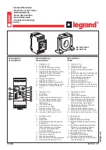
Summary of Contents for HFA151

Page 1: ...GEK 45484B INSTRUCTIONS MULTI CONTACT AUXILIARY RELAY TYPE HFA151 GE Protection and Control 205 Great Valley Parkway Malvern PA 19355 1337 Courtesy of NationalSwitchgear com ...

Page 2: ... to cover all details or variations in equipment nor provide for every possible contingency to be met in connection with installation operation or maintenance Should further information be desired or should particular problems arise which are not covered sufficiently for the purchaser s purposes the matter should be referred to the General Electric Company To the extent required the products descr...

Page 3: ... operated continuously near maximum ambient temperature APPLICATION The Type HFA151 relays are intended for application where i t is necessary to perform up to six auxiliary functions simultaneously by the operation of a single auxiliary relay I f more than six circuits are to be controlled the coils of two HFA relays may be connected in series DC only or in parallel RATINGS HFA151 relays are avai...

Page 4: ...pickup times times to close a normally open contact are 33 milliseconds or less for AC relays and 84 milliseconds or less for DC relays BURDENS Burdens with the relay in the picked up position and at rated voltage are 1isted in Tabl e I I I TABLE I I I DC COILS AC COILS WATTS FREQUENCY CYCLES VOLT AMPERES COLD HOT WATTS 7 8 6 0 50 23 9 60 32 12 CONSTRUCTION The HFA151A F and HFA151B F relays are a...

Page 5: ...relays are not to be installed immediately they should be stored in their original cartons in a place that is free from moisture dust and metallic chips Foreign matter collected on the outside of the case may find its way inside when the cover is removed and cause trouble in the operation of the relay ACCEPTANCE Check the nameplate stamping to make sure that the model number and rating of the rela...

Page 6: ...erience to select the test interval best suited to his individual requirements it is suggested that the points listed under INSTALLATION be checked on the same schedule as the associated protective relays If maintenance or readjustment is required see the section on SERVICING SERVICING CONTACT CLEANING For cleaning relay contacts a flexible burnishing tool should be used This consists of a flexibl...

Page 7: ...ake approximately simultaneously 0 008 when the relay is operated by hand All normally open contacts must have a wipe of 3 64 to 3 32 inches The contact gap must be approximately 7 32 inch This can be adjusted as follows a i Insert a 0 058 gage between the armature and pole face and close the armature i i Bend the left hand moving contact to just light the continuity lamp i i i Remove the 0 058 ga...

Page 8: ...imately 1 8 inch gap between the stop screw and armature Lock the stop screw 1 n this position Recheck pickup after the above changes or adjustments i 4 RENEWAL PARTS It is recommended that sufficient quantities of renewal parts be carried in stock to enable the prompt replacement of any that are worn broken or damaged When ordering renewal parts address the nearest Sales Office of the General Ele...

Page 9: ...GEK 45484 t M m i t iUEmiC M P D nuns SUiUTW L 2f t F t Semi flusb Mounting for With Flange cted Relay View BacR eon HFM 51 Front 8042731 1 Figure 9 Courtesy of NationalSwitchgear com ...

Page 10: ...GEK 45484 41 t t Side View HFA151 Relay 2 8042732 Figure 10 Courtesy of NationalSwitchgear com ...

Page 11: ...GEK 45484 Figure 3 8025264 HFA151 Front connected Relay for Surface Mounting Front View 11 Courtesy of NationalSwitchgear com ...

Page 12: ...5 13 r C rO i r O r 6 h i _ OPER POS PCS POS POS POS POS COIL 2 1 3 5 4 O o 4 10 KD CH u 9 6 tf 8 12 Figure 4 0104A8526 7 Internal Connections Diagram for HFA151 Relays Front View 12 Courtesy of NationalSwitchgear com ...

Page 13: ... 1 1 F 3 7 1 T 4 1 Fi 6 4 i F r 3 3E Fi I 4 6 y I r 4 J 3 r o 13 JUMPER M TOP OF RELAY t 7 17 f 3l POS POS POS POS f 4 POS ci POS bR HFA5IS ONLY 18 6 5 3 4 2 f 4 t l 1 14 o o EXT 4 10 L 01 A oJ L O CH O RES 5L _ i h 5 A 16 2 6 8 12 8 4 HOLES PANEL DRILLING INTERNAL CONNECTION BACH V I E W POSITIONS 5 AND 2 ARE OMITTED IN saw as Figure 5 K 6178972 9 Outline and Panel Drilling for Semi flush Mounted...

Page 14: ... 1 J EXT 434JUMPER o o o 9 16 OPER 17 COIL 0M T FOR FOUR C I R C U I T RELAY oj 16 3 jjHA 3 O P0S P0S 3 P0 S P0S P0S P0S HFA5IS ONLY 1 32 6 5 3 4 2 1 f 1 7 01A CO 1 V 16 14 KO O EXT 7 4 10 L o RES 8 1 2 INTERNAL CONNECTIONSCREAR VIEW P O S I T I O N S 5 AND 2 ARE O M I T T E D I N FOUR C I R C U I T RELAYS EACH CONTACT CONVERTIBLE ACCORDING TO CUNTACT ARRANGEMENT C00E o o 32 2 6 I 9 4 1 6 J O o o ...

Page 15: ... I j Yfm a t A fM N C 43 32 BD A 2 HOUES m ts i 1 I fil 632 to 23 232 CO 2 7T 21 i 4 15W i 17 32 I II 111 14108 6 42 52 r SU PANEL ORILLIA 3Jy 6 32 FRONT VIEW 12 OU LINE Figure 7 0104A8526 7 Outline and Panel Drilling for Front Connected Type HFA151 Relay 15 Courtesy of NationalSwitchgear com ...

Page 16: ...å å å å 3RZHU 0DQDJHPHQW 215 Anderson Avenue Markham Ontario Canada L6E 1B3 Tel 905 294 6222 Fax 905 201 2098 www ge com indsys pm Courtesy of NationalSwitchgear com ...

Reviews: