background image

Reference Manual

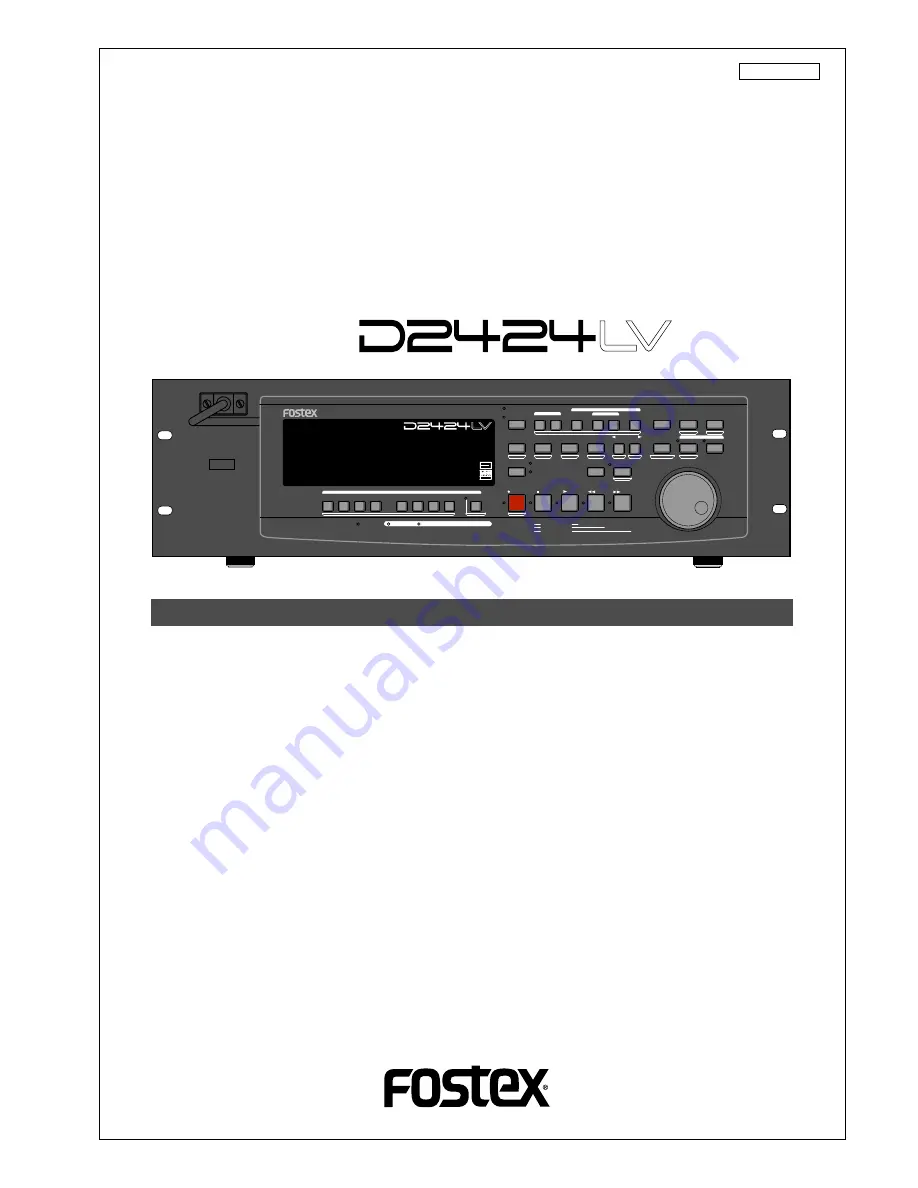
24 Track Digital Recorder

Model


8288 488 000

Introduction

Thank you for purchasing the Fostex D2424LV.
The D2424LV is a digital recorder using a 3.5 inch E-IDE hard disk recording media for recording/
playback/editing in 24 real tracks plus 32 additional tracks.
In addition to non-compression recording at quantization 16 bit/44.1kHz or 48kHz, 24 bit/44.1kHz
or 48kHz, 24 bit/88.2kHz or 96kHz, the D2424LV is also equipped with adat input/output (by
switching from S/P DIF).
Besides analog simultaneous record/playback, because it also complies with digital recording (S/P
DIF or adat) using DATA input/output and simultaneous recording of analog input plus digital input
(S/P DIF or adat), a full digital recording system can be built by combining the D2424LV with various
digital mixers.
In regards to save/load of song data, in addition to using adat digital signals and S/P DIF digital
signals, high speed backup of FDMS-3 Ver. 3.0/WAV file through the standard feature SCSI connec-
tor, is also possible.
Furthermore, by installing an optional Model 9044 (BAY+CADDY), an E-IDE hard disk for backup or
the optional Model 9046 (DVD-RAM drive) can be installed enabling high speed backup of FDMS-3
Ver. 3.0/WAV files.
For optional units, Model 8346 TC/SYNC card is available and these will also comply to phasing of
the standard feature WORD clock and also phasing against slave control by external LTC and VIDEO
reference signals.
Please carefully read through this manual together with the separate "

Quick Operation Guide

" for long

and satisfying operation of this equipment.

POWER

HOLD

RECORD

STOP

PLAY

REW

F FWD

ALL INPUT

ALL READY

LOCATE REC END

VARI PITCH

PUNCH

LOCATE

REHEARSAL

TAKE

RECALL

STORE

EXIT/NO

EXECUTE/YES

PGM SEL

NEXT

PREV

UNDO/REDO

PREVIEW

EDIT

SETUP

AUTO RTN

OUT

IN

AUTO PLAY

START

OUT

IN

END

17-24

ACCESS

9-16

1/9/17

2/10/18

3/11/19

4/12/20

5/13/21

6/14/22

7/15/23

8/16/24

FOOT SW

LOCATE ABS 0

CLIPBOARD PLAY

AUTO

TRACK SHIFT

SHIFT

DISP SEL

CHARACTER

TIME BASE SEL

P.EDIT

EJECT

ENVELOPE

CHASE

TC READY

TC GEN

M.UNDO

TRACK SHIFT

PREV TC

NEXT TC

RECORD TRACK

CLIPBOARD

AUTO PUNCH

AUTO RTN

LOCATE MEMORY

24bit

96kHz

OPTICAL

24TRACK DIGITAL RECORDER

Summary of Contents for D2424LV MKII

Page 1: ...SI connec tor is also possible Furthermore by installing an optional Model 9044 BAY CADDY an E IDE hard disk for backup or the optional Model 9046 DVD RAM drive can be installed enabling high speed backup of FDMS 3 Ver 3 0 WAV files For optional units Model 8346 TC SYNC card is available and these will also comply to phasing of the standard feature WORD clock and also phasing against slave control...

Page 2: ...n equilateral triangle is intended to alert the user to the presence of uninsulated dangerous voltage within the product s enclosure that may be of sufficient magnitude to constitute a risk of electric shock to persons The exclamation point within an equilateral triangle is intended to alert the user to the presence of important operating and maintenance servicing instructions in the literature ac...

Page 3: ...isk 31 Formatting a brand new hard disk Current drive 32 Reformatting the current drive or newly formatting the backup drive 33 Formatting a backup disk SCSI disk or optional DVD RAM disk 33 Optimizing the disk 34 Formatting and Optimizing disks 31 Time Base 24 Recording method and REMAIN indicator 25 Managing songs by program change function 26 Real tracks and Additional tracks 27 Input monitorin...

Page 4: ...62 Digital scrubbing using the envelope function 62 Cue ReviewFunction 62 Setup of the Chain Play List 59 Setup of the Chain Play Mode 60 Specify the Program and Execute Chain Play 61 ChainPlayFunction 58 Direct Locate 55 Auto Play function 56 Auto Return function 56 Auto Repeat function 57 LocateFunction 55 Storing and editing the locate points to the memory keys 52 Storing in real time 52 Editin...

Page 5: ...g of WAV files 102 Loading WAV files 104 Saving and Loading Song Data 87 MIDI clock sync system 77 Connecting external equipment 77 Setup of the recorder 78 Confirming the MIDI clock sync 78 Executing of recording 79 MTC sync MIDI machine control system 79 Setup to external equipment 80 Setup of external equipment 80 Setup of the recorder 80 Confirming MTC sync MMC 81 Executing of recording 81 Mul...

Page 6: ...Output 119 Setting BAR BEAT Resolution Mode 120 Setting the MIDI Device Number 121 Setting the Operating Clock 122 Checking the Number of Track Events 123 Setup of the Auto EE mode 124 Setup of the Foot switch function 124 Setup of the stop function at the mark point 125 Setup input output Balance Unbalance 126 Drive Format Information 127 Drive Setting 129 Setup of the display contrast level 130 ...

Page 7: ...ting a non DAT or adat SCSI backup drive WAV file Save Load is possible by using a DOS formatted SCSI type disk The unit s recorder section uses a recording format called FDMS 3 Ver 3 0 Fostex Disk Management System 3 It uses an E IDE hard disk as the recording media Save load of FDMS 3 or WAV file is possible by using the E IDE hard disk for backup or the optional DVD RAM drive Model 9046 In addi...

Page 8: ...rder Before you change the location of the recorder pack the recorder in the shipping carton or an impact resistant case Make sure that the recorder is kept free from external vibration or impact since the recorder is very sensitive to vibration Do not install the recorder in locations subject to the following Extremely high or low temperature or significant changes in temperature Excessive humidi...

Page 9: ...W EDIT SETUP AUTO RTN OUT IN AUTO PLAY START OUT IN END 17 24 ACCESS 9 16 1 9 17 2 10 18 3 11 19 4 12 20 5 13 21 6 14 22 7 15 23 8 16 24 FOOT SW LOCATE ABS 0 CLIPBOARD PLAY AUTO TRACK SHIFT SHIFT DISP SEL CHARACTER TIME BASE SEL P EDIT EJECT ENVELOPE CHASE TC READY TC GEN M UNDO TRACK SHIFT PREV TC NEXT TC RECORD TRACK CLIPBOARD AUTO PUNCH AUTO RTN LOCATE MEMORY 24bit 96kHz OPTICAL 24TRACK DIGITAL...

Page 10: ... when the hard disk is writing or reading data Same as the ACCESS LED on the detachable remote controller 4 Lock Unlock key When you remove or install the hard disk cartridge you need to lock unlock here using the included key 5 Hard disk power LED Green This LED lights up if the hard disk operates correctly when you turn the power on to the recorder 6 Removable hard disk cartridge slot This slot ...

Page 11: ...mode playback will start automatically after the START point is located This function is effective at any locate points other than the REC END point Auto Return mode When the END point is reached during playback the START point is automatically located in this mode This function is effective only when the START and END points have been specified Detachable Controller section Note The Auto Return f...

Page 12: ...ocating the CLIPBOARD OUT point Refer to page 68 for copying moving data Refer to page 64 for previewing data at the CLIPBOARD OUT point 7 Auto Return Start key AUTO RTN START PREVIEW This key is used to store and recall the start point AUTO RTN START point for the Auto Return or Auto Repeat operation You can locate a stored AUTO RTN START point If you press the AUTO RTN START key while holding do...

Page 13: ...o the MIDI clock and Song Position Pointers created on the internal Tempo Map 10 Auto Return End key AUTO RTN END PREVIEW This key is used to store and recall the end point AUTO RTN END point for the Auto Return or Auto Repeat operation You can locate a stored AUTO RTN END point If you press the AUTO RTN END key while holding down the SHIFT key when the recorder is stopped you can preview the fade...

Page 14: ... inputting character in the title edit mode this serves as a character short cut function The memory number selecting during display of Press LOCATE the memory number can be reverted with each press of this key With an optional Model 8346 TC SYNC card installed if this key is pressed while pressing down the SHIFT key the recorder will locate from the currently recorded time code to the head of the...

Page 15: ... data stored in the LOCATE key as data in memory number 00 Therefore it is possible to press this key alone to repeatedly LOCATE the same point These data can be individually stored in programs P1 P99 The data for each program is SAVED or LOADED for each program when the song data is designated for SAVE LOAD in the SETUP mode This data is maintained even when the power is turned OFF Refer to page ...

Page 16: ... Note This key is enabled only when the recorder is stopped 30 Auto Punch Mode On Off key AUTO PUNCH Switch this key ON for auto punch in out When you press this key while a correct value is stored to the AUTO PUNCH IN key and the AUTO PUNCH OUT key both the REHEARSAL LED and TAKE LED will blink indicating that Auto Punch mode is on If a correct value is not stored pressing the AUTO PUNCH key will...

Page 17: ...7 for details on the SETUP mode Refer to the APPENDIX at end of this manual in regards to the TC generator mode Refer to page 66 for details on multiple undo function Refer to the Quick Operation Guide in regards to editing of Vari Pitch data Refer to page 64 for details on preview Refer to page 62 for details on the envelope function Enters the vari pitch data editing mode 36 Meter display This m...

Page 18: ... of recorders 10 REMOTE INPUT terminating switch 100Ω This REMOTE INPUT terminating switch 100Ω is switched ON for normal use of an inputted RS 422 control signal into the REMOTE INPUT connector When controlling a multiple number of recorders the last one only is switched ON the others are switched OFF Note Always plug the power cable to the recorder before plugging the cable into the wall outlet ...

Page 19: ...nt digital mixer etc Depending on usage the appropriate connectors should be used as follow Refer to page 87 for information about LOAD function Refer to page 45 for information Digital Recording 13 MIDI Input Output Thru connector Connector DIN 5 pin MIDI INPUT Connect the MIDI OUTPUT connector of an external MIDI device here The recorder can be controlled remotely via an external MMC MIDI Machin...

Page 20: ...ill cause the recorder to locate the position of the displayed time or the bar beat clock value This message indicates that an operation such as copy move and paste has been completed F S M H DIGITAL 42 OL 0 30 24 18 12 9 6 3 DIGITAL MIDI kHz EXT FS CLOCK BIT SETUP MB SF DIGITAL VIDEO INT WORD 16 1 PGM 24 CHASE TC RDY 42 OL 0 30 24 18 12 9 6 3 CLK BAR LTC MTC IN ABSCHASE OFFSET LOCATE GEN UB REMAI...

Page 21: ...card is installed and the reference TC is switched to LTC and an external TC is input that reference input LTC time figure will be displayed MTC IN display 3 Switching the display using the DISP SEL key Let s assume that you turned off the power while the time display was using a time base of ABS and then you turned the power on again The recorder time display will again use a time base of ABS If ...

Page 22: ...ram duplicating are exempted For initial setup when producing a new program the initial setting of the currently active program is directly copied For example if there is a randomly set tempo map in the current program that tempo map setting will be copied as the tempo map for the new program This is convenient for producing a new program with the same setting as previously made music Display of v...

Page 23: ...d disk is not connected correctly No disk error display This is displayed when the removable disk is incorrectly set in the SCSI device Recording Disable Recording is disabled Action to take Correctly set the E IDE hard disk again Action to take Reset the removable disk Action to take Change the Off recording Rec Protect setting in Setup mode 42 OL 0 30 24 18 12 9 6 3 kHz 24 FS BIT 24 42 OL 0 30 2...

Page 24: ...dditional tracks 5 Input monitoring and playback monitoring 6 Audio file and Event Time Base The word Time Base appears frequently in this manual The concept of Time Base is similar to a tape counter on a conventional tape based multitracker in that it indicates the precise position of the recorder transport section the current position The recorder offers three types of Time Base ABS Absolute typ...

Page 25: ...unt but the recorder will not access the disk However MTC will be output when you try to play this area On the recorder the top of the disk is called ABS 0 and the recording end point is called REC END REMAIN indicator The REMAIN indicator displays available recording time expressed in time value ABS or MTC or bar beat clock BAR BEAT CLK value depending on the currently selected Time Base It also ...

Page 26: ... program number such as P01 shown in the example below Refer to page 37 for more information on the program select function Refer to page 36 for more information on the duplicating a program Refer to page 37 for more information on the program delete function Refer to page 38 for more information on the editing a program title In regards to the Chain Play menu in the SETUP mode see page 58 Refer t...

Page 27: ...t or the reverse However care must be taken when converting the format Refer to the SETUP mode in page 133 for details Track composition of a D2424LV formatted in 96kHz 24bit or 88 2kHz 24bit will be 8 Real Tracks 48 Additional Tracks Notes You cannot record data on Additional tracks in real time Also you cannot play back data on Additional tracks as is in real time If you wish to play back data o...

Page 28: ...ORD button READY tracks will enter the recording mode the READY track LED change to constant light and the RECORD LED will be lit Simultaneous with entering the recording mode READY tracks will be input monitoring and recording can be done while monitoring the recording sound at the recorder output The following example shows track 5 in Input Monitoring mode and other tracks in Playback Monitoring...

Page 29: ...eated since silence does not create data 0 However during S P DIF and adat digital recording the recorder records data 0 this is called mute recording When one second of consecutive data 0 is input to the recorder it creates a 0 file and limits the consumption of disk space However repeating this operation will eventually increase the number of events leading to event number overflow What is an ev...

Page 30: ...udio files are optimized into one continuous audio file in some cases Set the Clipboard In point and the Clipboard Out points within an unrecorded range to copy the area the area that contains multiple audio files and you wish to optimize between them then paste the data starting from the same Clipboard In point Multiple audio files within this range will become a single audio file 0 File Audio Fi...

Page 31: ...hether you format a new disk or reformat an old disk With this simple format type the recorder assumes that all sectors on the hard disk are of good quality Time required for formatting is shorter but any bad sectors would not be detected Select this format type when you format a brand new disk for which Fostex has confirmed quality operation You can select this format type only when you format a ...

Page 32: ...EXECUTE YES key The recorder starts formatting the disk and displays the size of the unformatted area on the target disk This value counts down as the formatting operation proceeds Wait until the format operation is complete 7 After formatting is complete press the EXIT NO key or the STOP button Available recording time after formatting A greater sampling frequency will reduce the available record...

Page 33: ...r cannot be selected Press the EXECUTE YES key while the present screen is shown in the display 6 Select the desired sampling frequency and bit resolution using the Jog dial and press the EXECUTE YES key The recorder displays the screen which enables you to set the Multiple Undo function on or off 7 Set the Multiple Undo function on or off using the Jog dial and press the EXECUTE YES key The recor...

Page 34: ...ake then optimize the disk For more information see Multiple Undo Function on page 66 After executing a format conversion via the Additional track format conversion menu in the SETUP mode the recorder will automatically enter the Disk Optimize menu Therefore we recommended that you optimize the disk immediately after format conversion By optimizing the multiple undo history of tracks 25 56 will be...

Page 35: ...r Upon starting up the recorder Initialize Current IDE Drv Hard disk model number Storage mode Standard format in this case messages are followed with an ABS time base then show the top of the Program ABS 0 At this time the current Program is indicated as P01 2 Press the PGM SEL key Select PGM appears on the display briefly then changes to a flashing 01 and SURE flash is the name of PGM 01 3 Turn ...

Page 36: ...s insufficient or if 99 programs have already been created you cannot create more new programs If a new program is attempted Can t New PGM will indicate that the operation is invalid 7 Press the EXIT NO key or STOP button Any program content Recording data various setup items can be duplicated but with a separate program number 1 With this recorder in the stop mode press the EDIT key to display PG...

Page 37: ...can be sure to select a Program before you start working Deleting a Program This section explains how to delete an unnecessary Program Deleting an unnecessary Program will expand the recordable area making your work flow more smoothly since recording or editing requires sufficient recordable area free space on the disk Use the Delete PGM menu in SETUP mode to delete a Program Notes on deleting a P...

Page 38: ...ecorder enters SETUP mode Be sure to select the desired Program using the steps explained in the Using the Program Change function section 1 Press the SETUP key while the recorder is stopped to put the system in the SETUP mode 2 Turn the Jog dial to select the first hierarchy level of the Title Edit flash menu Flashing Flashing Flashing 42 OL 0 30 24 18 12 9 6 3 kHz 24 FS BIT SETUP 24 42 OL 0 30 2...

Page 39: ...XECUTE YES key Either 44 1 or 48 can be selected in a 16 bit program and any one of 44 1 48 88 2 96 can be selected for a 24 bit program Pressing the EXECUTE YES key will set the selected FS and change the display to the Sample Rate menu 4 Press the EXIT NO key or the STOP button The recorder will change to the head ABS 0 of the Normal display Note If you change the FS 44 1 or 48kHz of a program i...

Page 40: ...ng you need to specify the Auto Punch In point recording start point and the Auto Punch Out point recording end point Preparation Storing the edit points 1 Refer to Storing the edit points to set the Auto Punch In Out points Store the Auto Punch In point to the AUTO PUNCH IN key and the Auto Punch Out point to the AUTO PUNCH OUT key Refer to page 51 for more information on storing the edit points ...

Page 41: ...cate the playback start point for rehearsal press the AUTO PUNCH IN key then press the LOCATE key The recorder displays the time position stored in the AUTO PUNCH IN key and locates the point and stops Press the REWIND button to go backward If you have set the preroll time as described on page 113 you can locate a point that precedes the Auto Punch In point by the specified preroll value Hint 2 Qu...

Page 42: ... fail with AUTO PUNCH IN OUT and are not satisfied repeat the process by performing the AUTO PUNCH IN OUT undo operations described in the next section Single Undo Redo You can single undo or redo Auto Punch In Out recording Press the UNDO REDO key after recording is complete to restore the conditions that existed prior to the recording Press the UNDO REDO key again to restore the conditions that ...

Page 43: ...input monitoring mode between the Punch In and Out points the points at which you press the foot switch and the sound is not recorded You can practice the Punch In Out operation repeatedly before you proceed to actual recording 1 Press the foot switch while holding down the STOP button Rehearsal On will appear on the display or about 1 second then rehearsal mode will appear and the REHEARSAL LED g...

Page 44: ...y again to restore the conditions that existed after the recording However the procedures explained here is for Single Undo Redo and there are limitations as written in the Notes below If the current drive was formatted with the multiple undo function ON Multiple Undo is also possible Refer to page 66 for details on the Multiple Undo function Notes at executing single undo redo Note 1 This functio...

Page 45: ...ow If the connected external device has only a COAXIAL RCA pin jack for digital output use an optional Fostex COP 1 96k optical coaxial converter OUTPUT DATA 16 9 24 17 8 1 INPUT 16 9 24 17 8 1 OUTPUT DATA 16 9 24 17 8 1 INPUT 16 9 24 17 8 1 Notes on interconnecting When using the D2424LV DATA INPUT connector it must be set for either S P DIF digital signals optical or adat digital signals via Set...

Page 46: ...l device Make sure that the level meter segments light up and move as the digital signal is being input Completing recording 4 After you finish recording stop the recorder and the connected digital equipment SPDIF Async S P DIF digital signals from DATA INPUT 1 8 will be assigned to tracks 1 and 2 and the digital equip ment is synchronized with the internal clock of the D2424LV SPDIF Sync S P DIF ...

Page 47: ...ck from WORD IN the recorder automatically synchronizes to the incoming clock while the DIGITAL and EXT indica tors light in the display When receiving word clock from WORD IN the recorder synchronizes to the incoming clock while the DIGITAL and EXT indicators light in the dis play Regardless of receiving or not receiving word clock from WORD IN the recorder synchro nizes to the external S P DIF d...

Page 48: ...n on the Program Select function Notes Connecting the recorder to an external digital device via both digital input and output jacks may generate a digital loop Data on the additional tracks cannot be digitally recorded to the external device as it is To output digital data from the additional track move it to the real tracks first then output it to the external device using the Track Exchange fun...

Page 49: ...track track 24 to which the metronome sound is to be output set to READY an attempt to record you cannot record to this track Also information which had already been recorded on this track cannot be played back Always switch off the Metronome function setting in the SETUP mode after finishing Please remember this In D2424LV which had been formatted to 96kHz 24bit or 88 2kHz 24bit Real track 1 8 th...

Page 50: ...mode recording does not take place and all other tracks will be in the reproduction monitor mode therefore track 24 plays back the metronome sound 8 Play the musical instrument in time with the metronome and adjust the recording level of the track to be recorded on the mixer 9 After adjusting the recording level stop the recorder and return to the top of the Program Starting recording 10 Hold down...

Page 51: ...oard during the Copy Paste or Move Paste operation Locating the CLIPBOARD OUT point Copy end point for copying or moving data to the clipboard during the Copy Paste or Move Paste operation Locating the AUTO RTN START point Locate end point from AUTO RTN END in Auto Return or Auto Repeat modes Locating the AUTO RTN END point Locate start point to AUTO RTN START in Auto Return or Auto Repeat modes N...

Page 52: ...TORE key is pressed while holding down the SHIFT key data to be registered will be held and be confirmed To register data after confirmation press the STORE key again and press the desired memory key Editing and storing data You can recall data stored in the memory key edit it and store it again F S M H 42 OL 0 30 24 18 12 9 6 3 kHz 24 FS BIT SF 24 42 OL 0 30 24 18 12 9 6 3 LOCATE 23 22 21 20 19 1...

Page 53: ...ata in the Memory key After editing the data the LOCATE key can locate that point or even be re stored as data for other Memory keys Notes The last data located with the Memory key or LOCATE key is constantly stored as LOCATE number 00 However this data is constantly replaced after every LOCATE command Therefore do not use Locate Number 00 for independent Locate data You cannot preview the data st...

Page 54: ...cation to edit cursor flashing point increase or decrease the number setting with the Jog dial or input the desired time base Flashing Flashing 4 Press the STORE key the STORE LED lights up The LOCATE number selection menu to store data will appear 5 You can use the Jog dial to input the desired LOCATE number 6 Press the LOCATE key The edit time data is stored as the time data for the selected LOC...

Page 55: ...n press the LOCATE key The recorder will locate the point edit point stored in the corresponding memory key immediately The located time data is always stored as time data in Locate Number 00 Specify the Locate Number to locate data 1 Press the RECALL key The Locate Number selection menu appears 2 Turn the Jog dial or press the NEXT key PREV key to select the desired number 3 Press the LOCATE key ...

Page 56: ...P mode so that the recorder will start playback preroll time before the locate point You can set the preroll time from 0 to 10 seconds Refer to the chapter Changing the Initial Settings SETUP Mode on page 113 Auto Return function This function allows the recorder to play data up to the AUTO RTN END point then automatically locate the AUTO RTN START point as shown in the diagram below To enable thi...

Page 57: ... you cancel the function by pressing the STOP button To enable this function both AUTO PLAY mode and AUTO RTN mode should be turned on and the AUTO RTN START point and the AUTO RTN END point should already be set Using this function will facilitate the Auto Punch In Out and Manual Punch In Out rehearsal See Hint after the following section Operation of the Auto Repeat mode 1 Store the AUTO RTN STA...

Page 58: ...e END point of program 02 started in playback the recorder will automatically playback in setup order between the START points END points and at the moment playback is finished at the END point of the last program 01 stops at the START point of the first program Repeat mode In the repeat mode playback is repeated until the above auto play mode is canceled Note If power is switched off and then swi...

Page 59: ...program 5 program 2 If the chain list is to be ended after program 1 as shown in the example below set EE at fourth c04 in the chain list By selecting EE the chain play list setting will be c01 c03 and beyond c04 will be invalid EE can be selected with the Jog dial while the right program number is flashing Note In order to execute chain play AUTO RTN START point and AUTO RTN END point must be set...

Page 60: ... OL 0 30 24 18 12 9 6 3 kHz 24 FS BIT SETUP 24 42 OL 0 30 24 18 12 9 6 3 23 22 21 20 19 18 17 16 15 14 13 12 11 10 9 8 7 6 5 4 3 2 1 CLOCK INT 42 OL 0 30 24 18 12 9 6 3 kHz 24 FS BIT SETUP 24 42 OL 0 30 24 18 12 9 6 3 23 22 21 20 19 18 17 16 15 14 13 12 11 10 9 8 7 6 5 4 3 2 1 CLOCK INT Flashing 4 Press the EXECUTE YES key after selecting the mode The recorder will exit from the SETUP mode after s...

Page 61: ...2424LV will locate to the AUTO RTN START point of the selected program 3 Start playback by pressing the PLAY button Chain play will be execute in compliance to the currently set Chain Play MD mode 42 OL 0 30 24 18 12 9 6 3 kHz 24 FS BIT 24 42 OL 0 30 24 18 12 9 6 3 23 22 21 20 19 18 17 16 15 14 13 12 11 10 9 8 7 6 5 4 3 2 1 CLOCK INT 42 OL 0 30 24 18 12 9 6 3 kHz 24 FS BIT PGM 24 42 OL 0 30 24 18 ...

Page 62: ...l You can use the Shuttle dial for 1 7 times or 1 8 times 1 Press the PLAY button to start playback 2 Turn the Shuttle dial clockwise during playback The forward direction cue speed variates from 1 7 times speed depending on the degree angle of turning the dial PLAY LED flashes and F FWD LED lights up during the cue process 3 Adjust the monitor sound of the track to monitor on the mixer 4 Let go o...

Page 63: ...ND LED and F FWD lights up 2 You can use the Jog dial to digitally scrub the performance of the track selected The envelope of the performance recorded on the track variates in real time During forward direction scrub the F FWD LED lights up and during rewind direction scrub the REWIND LED lights up 3 Adjust the monitor sound of the selected track so that it can be monitored on the mixer 4 Press t...

Page 64: ...ack the rise sound at the locate point edit point As shown in the diagram one second of data prior to the locate point is muted during playback The mute is off fade in at the locate point and the sound is played back for one second The recorder will repeat this operation until you quit the Preview function Display indication during the Preview operation The recorder repeats playback of the fall so...

Page 65: ...int stored in the memory keys while previewing the sound Use this function to change the Auto Punch In Out points the start point of Copy Paste and Move Paste and the start and end points of the Erase function Notes You can audition the result of trimming during the next preview That is if you trim the position while previewing the sound for the first time you can check the result when you preview...

Page 66: ...mp of the internal clock e g 10 50 37 11 Dec Therefore you can always recall the desired take This is quite different from the Single Undo Redo function Completion data and time of Take 2 Completion data and time of Take 3 Completion data and time of Take 4 Completion data and time of Take 5 Completion data and time of Take 6 Notes regarding the Multiple Undo operation The time stamp of each take ...

Page 67: ...sk using the Disk Optimize menu in Setup mode However remember that if you optimize a current drive disk that recorded several takes only the most recent take will remain and other takes will be erased If you wish to keep other takes follow the procedure below then optimize the disk Keeping only one take First apply the Multiple Undo function to the take you wish to keep then optimize the disk For...

Page 68: ...on However they are different as shown in the diagram Remember this difference when you start using these functions Copy Paste Using the Copy Paste function enables you to copy a specific range of data from a specific track to the clipboard as shown below this is called Copy Clip operation on the unit then paste the data at a specific point in a specific track The number of copy source tracks and ...

Page 69: ...rmation Executing Copy or Move 1 Press the RECORD TRACK select key of the copy or move source track to set it READY Select from mono tracks or adjacent odd even tracks 1 2 3 4 5 6 etc 2 Press the EDIT key repeatedly until Copy Clip or Move Clip flashes on the display Select Copy Clip to execute Copy Paste Select Move Clip to execute Move Paste Note If you select non adjacent tracks such as track 1...

Page 70: ...LETED Track display of the item to be copied or moved will change to lit 42 OL 0 30 24 18 12 9 6 3 kHz 24 FS BIT 24 42 OL 0 30 24 18 12 9 6 3 SURE 23 22 21 20 19 18 17 16 15 14 13 12 11 10 9 8 7 6 5 4 3 2 1 CLOCK INT Flashing Checking the clipboard data Hold down the STOP button and press the PLAY button The recorder indicates whether the sound data on the clipboard is a copied data or moved data ...

Page 71: ...ng mode by pressing the EDIT key Copy Paste will be displayed after pressing the EDIT key Next specify the track and amount to be pasted and execute paste Checking the clipboard data Data copied to the clipboard can be confirmed even after switching the program by the above procedure For example when a specific data in Program 1 is copied to the clipboard and then switched to Program 2 in which it...

Page 72: ...cified point to REC END You may erase all data in the range from a specified point to REC END in the currently selected Program You can erase data on a mono real track or multiple real tracks To erase data on an additional track you need to move the data to a real track then erase it When you erase all tracks data the REC END point will move backward However if you erase data on a mono track or mu...

Page 73: ...Paste or Move Paste To erase the data in its entirety from ABS 0 REC END it is recommended that erase end point AUTO PUNCH OUT point is stored after the REC END time to ensure through erase performance To do this move the recorder section location to the REC END point prior to storing the AUTO PUNCH OUT point press the PLAY button from that location move the ABS time after the REC END and store Th...

Page 74: ...24 18 12 9 6 3 kHz 24 FS BIT 24 42 OL 0 30 24 18 12 9 6 3 23 22 21 20 19 18 17 16 15 14 13 12 11 10 9 8 7 6 5 4 3 2 1 CLOCK INT 42 OL 0 30 24 18 12 9 6 3 kHz 24 FS BIT 24 42 OL 0 30 24 18 12 9 6 3 23 22 21 20 19 18 17 16 15 14 13 12 11 10 9 8 7 6 5 4 3 2 1 CLOCK INT Exchange in 8 track units Exchange in 2 track stereo pair units Exchange in mono track units Exchange in 8 track units 1 In the stop ...

Page 75: ...o entering the edit mode Regardless as to whether Exch 01 08 09 16 or Exch 09 16 01 08 is input there will be no difference in the fact that tracks 1 8 and tracks 9 16 have been exchanged Exchange in mono track units 1 Upon display of the previously mentioned TRK Exch Mono then pressing the EXECUTE YES key the display will change as shown below This display indicates that at present tracks 1 and 2...

Page 76: ...01 in TRK 01 will flash 3 Rotate the Jog dial while 01 is flashing to select the desired track number and press the EXECUTE YES key The flashing number will move to the left end digit to allow input of new letters and symbols In example below will flash 4 Numbers and symbols can be input at the selected flashing digit by rotating the Jog dial and the flashing digit can be moved with the Shuttle di...

Page 77: ...SOLO EQ EDIT EQ EDIT EQ EDIT EQ EDIT EQ EDIT EQ EDIT EQ EDIT EQ EDIT SOLO ON ON SOLO STORE RECALL EQ ON STORE RECALL STORE RECALL SOLO 1 1 DATA EXIT ENTER MASTER 15 14 13 12 11 10 9 1 8 ANALOG IN 9 16 ADAT IN 17 20 EFF RTN AUX1 AUX2 AUX3 AUX4 EFF1 EFF2 ADD AUX 10 0 10 20 30 40 ADAT IN 0 10 20 30 60 40 PAN PAN PAN PAN PAN PAN 40 36 24 18 12 9 6 3 OL ST BUSS SOLO L R METER CHANNEL FADER MODE KEY MOD...

Page 78: ...o map is made in steps 2 and 3 Initial setting 001 bar 1st meter Tempo120 Permissible bar setting Follows the previous Setup of the time signature Permissible signature setting Follows the previous Setup of the time signature Permissible setting of tempo Quarter note 30 250 Tempo elimination Permissible setting of maximum number of points 64 points This item can be set for each program The setting...

Page 79: ...e the Fostex Exclusive List on page 135 Set the recorder in the initial state Confirm the program and sampling frequency MIDI IN MIDI OUT MIDI IN Q FREQ GAIN Q FREQ GAIN Q FREQ GAIN 10 0 10 20 30 40 10 0 10 20 30 40 10 0 10 20 30 40 10 0 10 20 30 40 10 0 10 20 30 40 10 0 10 20 30 40 10 0 10 20 30 40 16 PAN Q PAN ON ON ON ON ON ON ON SOLO SOLO SOLO SOLO SOLO SOLO SOLO EQ EDIT EQ EDIT EQ EDIT EQ EDI...

Page 80: ...ing will be held even though power is switched OFF Refer to page 115 SETUP mode MTC offset time setting for operating procedure 3 In the SETUP mode MTC offset mode setting whether the MTC offset time setup in Step 2 should be output ABS at the ABS 00M 00S 00F 00SF position or at the 001BAR 1BEAT 00CLK bar signature must be selected Initial setting ABS Permissible setup item ABS Bar Beat This item ...

Page 81: ...rst bar and therefore it can be made to sync from the head of the tune Offset mode For BAR BEAT As mentioned before because the ABS 0 position is set at the 002BAR 1BEAT 00CLK position the setup MTC offset time can be set to the head of the tune without taking into account the time until reaching sync as mentioned above The length of the time two bars beforehand will change in accordance to the fi...

Page 82: ...D STOP PLAY REW F FWD ALL INPUT ALL READY LOCATE REC END VARI PITCH PUNCH LOCATE REHEARSAL TAKE RECALL STORE EXIT NO EXECUTE YES PGM SEL NEXT PREV UNDO REDO PREVIEW EDIT SETUP AUTO RTN OUT IN AUTO PLAY START OUT IN END 17 24 ACCESS 9 16 1 9 17 2 10 18 3 11 19 4 12 20 5 13 21 6 14 22 7 15 23 8 16 24 FOOT SW LOCATE ABS 0 CLIPBOARD PLAY AUTO TRACK SHIFT SHIFT DISP SEL CHARACTER TIME BASE SEL P EDIT E...

Page 83: ...ating procedure and details 2 Set the SETUP mode MTC offset mode setting to the same mode as in the recorder 1 Refer to page 116 SETUP mode MTC offset mode setting for operating procedure and details 3 Set the SETUP mode MTC offset time setting to the same offset time as in the recorder 1 Refer to page 115 SETUP mode MTC offset time setting for operating procedure and details 4 Set the SETUP mode ...

Page 84: ...he master will be interrupted CHASE in the display will change from lit to blinking 4 During FF REW the master only will be in the FF REW mode and the slaves will remain stopped but when playback recording is started the slaves will immediately chase lock Note The unit re chase window is fixed at 10 frame In other words when MTC of the master and slave drifts apart more than 10 frames it will assu...

Page 85: ...al of the respective equipment for details Setup of the D2424LV 1 Set to same frame rate as the sequence software by the SETUP mode MTC Frame rate setting Refer to page 114 SETUP mode MTC Frame rate setting for operating procedure and details 2 Set to the desired mode by the SETUP mode MTC offset mode setting Refer to page 116 SETUP mode MTC offset mode setting for operating procedure and details ...

Page 86: ...splay will change from lit to blinking 3 During FF REW of the sequence software the recorder will remain stopped but upon starting to record the recorder will immediately chase lock Note Chase lock of the recorder by MTC only is permissible when speed difference of the MTC from the master is within 5 6 Against the MTC within this range variable pitch will be constantly applied internally for chasi...

Page 87: ...g data in the current drive is output to a connected DAT Two tracks of audio data shown in black in the diagram are output To save data from Real tracks 1 24 two track data will be output twelve times which takes twelve as much time as the song duration ABS 0 to REC END To save all data including Additional tracks 1 56 two track data will be output twenty eight times which takes twenty eight times...

Page 88: ...and the lower 4 bits will be 0 Note when saving data using DAT or adat Song data can be saved as a real track additional track or ALL data Please note the following points when saving song data using a DAT or adat device The save time of the data depends on the time of the song data ABS 0 REC END on the real track Therefore if you attempt to save data that exists on an additional track that is lon...

Page 89: ...output and input connectors on the recorder to the input and output connectors on the external digital device respectively may generate a digital loop Setting up an external device 1 Set the same sampling rate to that of the recorder 2 Select digital input on the external device so that the external device will accept a digital signal On some external devices you may have to set up so that the ext...

Page 90: ...al input signal and start recording on the external device DAT or adat Setting a START ID DAT or a locate point at the recording start point will facilitate future loading operations 11 Confirm that the recording on the external device has started and press the EXECUTE YES key The save operation starts and the time required for the save operation appears on the display and a few seconds later it w...

Page 91: ...cted device If the external device has only COAXIAL type RCA digital I O connectors connect an optional COP 1 96k optical coaxial converter to use an S P DIF digital signal Connecting both output and input connectors on the recorder to the input and output connectors on the external digital device respectively may generate a digital loop Setting up an external device 1 Setup the external device so...

Page 92: ...will flash and warn you if the sampling frequency of the recorder and DAT vary when loading with S P DIF digital signals Be careful when setting the sampling frequency for adat digital signals because there will be no FS warning though there may be a discrepancy 9 Press the EXECUTE YES key again Start Player Start playing the recorder appears on the display 10 Play the corresponding external devic...

Page 93: ... to connect a SCSI device to a D2424LV Notes on connection Before making connections make sure that both the recorder and the SCSI drive are turned off One SCSI drive may be connected on the recorder The SCSI connector on the recorder is a half pitch 50 pin connector compatible with Macintosh computers Use a cable with connectors that conform to the standards for connecting a SCSI drive The SCSI d...

Page 94: ...pears 8 Press the EXIT NO key or the STOP button to quit the SETUP mode The recorder returns to the ABS display of the Program that was selected before it entered Setup mode Your backup purpose SCSI disk has been formatted after completing the steps up to this point The SCSI disk is now ready to SAVE LOAD To continuously format another disk remove the disk from the SCSI drive and then repeat the s...

Page 95: ... of disks necessary This indicates that 2 disks are necessary to execute the save procedure Output format available adat SPDIF SCSI IDE2 Programs available When using an adat SPDIF P01 P99 each program individually When using a SCSI IDE2 P01 P99 or All program Track available When using an adat or DAT Tracks 1 8 1 16 1 24 1 32 1 40 1 48 1 56 9 16 9 24 9 32 9 40 9 48 9 56 17 24 17 32 17 40 17 48 17...

Page 96: ...ompt is asking you whether you want to erase the existing data saved on the disk that was inserted and indicates that you have entered the Delete PGM menu in the SETUP mode If it is okay to erase that disk press the EXECUTE YES key The Delete ALL PGM message will appear Press the EXECUTE YES key to delete all programs Save is automatically resumed after the programs are deleted If it is not okay t...

Page 97: ...re different such as 05 08 in the display of Save All it could not be saved in one disk and indicated that a multiple number of disks were required For example if save was executed while Save All 05 08 was displayed programs 1 5 could be saved in the first disk but programs beyond 6 had to be saved in another disk In this case if save is continued in the second disk the same B01 backup number 01 f...

Page 98: ...r the load destination the existing data is deleted while loading takes place If you do not want to overwrite the existing data select New PGM mentioned above prior to loading 4 Press the EXECUTE YES key after selecting the program Loading is started and the display will show B P MB This indicates that the backup data B on the SCSI hard disk is being loaded on the current drive program P The MB lo...

Page 99: ... INT 3 Turn the Jog dial to IDE2 so that it flashes Then press the EXECUTE YES key Find IDE2 Device Name The backup mode selection menu appears FDMS3 flashes in the default mode 42 OL 0 30 24 18 12 9 6 3 kHz 24 FS BIT SETUP 24 42 OL 0 30 24 18 12 9 6 3 23 22 21 20 19 18 17 16 15 14 13 12 11 10 9 8 7 6 5 4 3 2 1 CLOCK INT 4 Press the EXECUTE YES key while FDMS 3 is flashing A menu appears so you ca...

Page 100: ...22 21 20 19 18 17 16 15 14 13 12 11 10 9 8 7 6 5 4 3 2 1 CLOCK DIGITAL INT 42 OL 0 30 24 18 12 9 6 3 kHz 24 FS BIT SETUP 24 42 OL 0 30 24 18 12 9 6 3 23 22 21 20 19 18 17 16 15 14 13 12 11 10 9 8 7 6 5 4 3 2 1 CLOCK INT IDE2 Device Name appears Then the menu to select the program to load appears You can select the Load All choice in addition to individual backup programs by turning the Jog dial at...

Page 101: ...kup disk WAV files that have been moved from the root directory to another location such as a different folder cannot be acknowledged by this recorder and could cause a malfunction FILE NAME OF THE WAV FILE WAV files saved by this recorder will be recorded under the file name of WAV WAV files which can be loaded by this recorder must have a file name of WAV The first 6 letters will be the title di...

Page 102: ...will flashes If the Jog dial is rotated at this stage in addition to All Trk flashing 01 01 flashing 56 56 flashing can be selected This function is used when specifying any desired track and saving it 7 After selecting the track press the EXECUTE YES key If All Trk or any desired track was selected the display will change to the following When All Trk is selected The display will change to making...

Page 103: ...o be able to add a new WAV file Press the EXECUTE YES key and after display of Disk Full Delete All WAV is displayed then press the EXECUTE YES key again and it will go to Step 7 for deleting all WAV files on the backup disk After save only saved WAV files will be recorded The last track can be selected After setting to 05 24 by rotating the Jog dial and pressing the EXECUTE YES key the display wi...

Page 104: ... files on the backup disk After save only saved WAV files will be recorded Loading WAV files WAV files will be loaded Prior to this make sure the backup disk is connected to the SCSI equipment The following explains how to use a backup disk in which WAV files were saved by this unit Loading from the E IDE hard disk for backup or the optional DVD RAM drive is possible by the same procedure 1 Enter ...

Page 105: ... selecting an existing program loading can be done in parallel with erasing super scripting this existing program Turn the Jog dial in this state to select the load destination track 01 56 are selectable with the above example If for example you select 01 05 it means Track 1 that is saved will be loaded to Track 5 that is specified as the load destination Flashing Flashing Flashing As an example i...

Page 106: ...ote WAV files which can be saved loaded by this recorder must have file names written as WAV Other file names cannot be acknowledged by this recorder Unknown file names will not be acknowledged and could cause malfunction Extreme care should be taken when changing file names and making folders on a computer The first six letters will be the title shown in the SETUP mode Title Edit display The last...

Page 107: ...ng BAR BEAT resolution mode Resolution Off 120 Setting the MIDI device ID number Device ID 00 121 Setting the operating clock Clock Sel Int 122 Setting the SYNC preset Sync Preset Available with option Model 8346 Refer to the APPENDIX Setting the Virtual LTC display Virtual LTC Available with option Model 8346 Refer to the APPENDIX Setting the chase offset display Offset Disp Available with option...

Page 108: ...rent drive disk Signature Set Setting a signature appears Otherwise the first hierarchy level of the previously selected SETUP menu appears To exit SETUP mode press the STOP button or the EXIT NO key Each time you press one of these keys the recorder returns to the previous hierarchy level of the menu and finally exits SETUP mode The title of the SETUP menu appears You can select a different menu ...

Page 109: ... OL 0 30 24 18 12 9 6 3 kHz 24 FS BIT SETUP 24 42 OL 0 30 24 18 12 9 6 3 23 22 21 20 19 18 17 16 15 14 13 12 11 10 9 8 7 6 5 4 3 2 1 CLOCK INT 42 OL 0 30 24 18 12 9 6 3 kHz 24 FS BIT SETUP 24 42 OL 0 30 24 18 12 9 6 3 23 22 21 20 19 18 17 16 15 14 13 12 11 10 9 8 7 6 5 4 3 2 1 CLOCK INT Flashing 3 Press the EXECUTE YES key The indication changes to 001 measure of 001bar 4 4 flashes You can enter a...

Page 110: ... data in the next step 3 Press the EXECUTE YES key The stored time signature and tempo data in its entirety are cleared and the initial settings are restored 4 Press the EXIT NO key or STOP button To cancel the All Clear operation press the STOP button or the EXIT NO key now Each time you press one of these keys the recorder returns to the previous hierarchy level of the menu and finally exits SET...

Page 111: ...ss the EXECUTE YES key Indication on the display changes as shown below and the current tempo appears The initial setting is 001 bar 1 120 This means that a tempo for the first beat of the first measure is set to 120 2 Rotate the Jog dial clockwise You can view the current tempo values in sequence Tempo value bar means that no tempo values are specified after the current setting With the initial s...

Page 112: ...k flashes then press the EXECUTE YES key The current setting Off or On appears on the display Pressing the EXECUTE YES key lights up the flashing character steadily the current setting flashes The initial setting is Off as shown below 3 Turn the Jog dial to select On or Off Selecting On will enable the output of the metronome sound Selecting Off initial setting will disable the metronome output 4 ...

Page 113: ... is stopped press the SETUP key to enter SETUP mode 2 Turn the Jog dial to select PrerollTime flashes then press the EXECUTE YES key The current preroll time setting appears on the display Pressing the EXECUTE YES key lights up the flashing character steadily the current setting flashes The initial setting is 00 as shown below 3 Turn the Jog dial to enter a desired preroll time value You can set a...

Page 114: ... below 3 Turn the Jog dial to select the desired MIDI sync signal Setting this parameter to CLK will select MIDI clock Song Position Pointer Setting the parameter to MTC initial setting will select MIDI time code With the Off setting no MIDI sync signal will be output 4 Press the EXECUTE YES key The selected MIDI sync signal type is stored and the recorder returns to the display with the flashing ...

Page 115: ... selected MTC for the Setting MIDI sync output signal menu With the initial setting of 00h 59M 57S 00F 00SF for example MTC of 59M 57S 00F 00SF is output at the ABS time 00M 00S 00F 00SF You can also set an offset value from the 001bar 1beat 00clk value bar beat on the Tempo Map Refer to the next section for information on MTC Offset mode Initial setting 00H 59M 57S 00F 00SF Setting range of offse...

Page 116: ...mpo of the software are slightly different even if both use the same tempo Some sequence software can read the tempo output from the recorder correctly We recommend that you use the tempo of the recorder on the sequence software No such problems will occur if the sequence software synchronizes the recorder via MIDI clock instead of MTC Initial setting ABS Offset mode option ABS or Bar You can set ...

Page 117: ...enter SETUP mode 2 Turn the Jog dial to select Slave Type flashes then press the EXECUTE YES key The current Slave type appears on the display Pressing the EXECUTE YES key turns off the flashing character and the Slave type indicator flashes With the initial setting Vari flashes as shown below 3 Use the Jog dial to select the desired Slave type Rotating the Jog dial clockwise and counter clockwise...

Page 118: ...digital mixer can be digitally recorded When selecting the clock there are the Async and Sync modes either should be selected depending on the application If it is set to Async mode the later explained Clock Sel Setting the operating clock should be setup in accordance to the application Initial setting Analog Assignable digital signal setting digital in clock adat Async adat digital signal Asynch...

Page 119: ...gnals to tracks 9 16 and 17 24 a total of 24 tracks can be recorded simultaneously To cancel the operation or to restore the setting obtained prior to the EXECUTE YES key press press the STOP button or the EXIT NO key Each time you press one of these keys the recorder returns to the previous hierarchy level of the menu and finally exits SETUP mode and displays the previous Time Base Setting digita...

Page 120: ...n you turn this mode on the CLK clock digits will be always round off to 00 and be stored in the memory key while the recorder is using the BAR BEAT CLK Time Base That is beat resolution is used Using this function allows you to automatically store a beat resolution value of the CLIPBOARD IN OUT points and other points in real time Press the STORE key then the corresponding memory key while playin...

Page 121: ...ge the recorder receives is 7F the recorder will recognizes it to perform the corresponding operation regardless of its device ID setting Initial setting 00 Options 00 99 This setting is shared by all Programs in the same disk The settings cannot be saved and loaded as part of the song data The settings are maintained after you turn off the power to the recorder Setting the MIDI device ID 1 While ...

Page 122: ... loaded as part of the song data The settings are maintained after you turn off the power to the recorder 3 With the Jog dial select the operating clock If Int initial setting is selected the recorder will operate using the internal clock If Auto is selected the recorder will sync to an external digital signal If Word is selected the recorder will sync to an external word clock signal 4 Press the ...

Page 123: ...tal In and the recorder ignores your operation no clock received from WORD IN no clock received from WORD IN clock received fromWORD IN When no word clock is received the recorder is referenced to the internal clock while the EXT in dicator flashes When no word clock is received the EXT indicator flashes showing that the recorder cannot be locked Checking the number of track events No Of Event men...

Page 124: ... 24 FS BIT SETUP 24 42 OL 0 30 24 18 12 9 6 3 23 22 21 20 19 18 17 16 15 14 13 12 11 10 9 8 7 6 5 4 3 2 1 CLOCK INT Setup of the Foot switch function Foot SW menu At the Setup of the foot switch function menu functions of a foot switch connected to the FOOT SW jack must be set up Functions of the foot switch are manual punch in out or PLAY STOP of D2424LV Initially this is set to the Punch in out ...

Page 125: ... will return to flashing 4 Exit from the SETUP mode by pressing the EXIT NO key or the STOP button Setting the stop function at the mark point 42 OL 0 30 24 18 12 9 6 3 kHz 24 FS BIT SETUP 24 42 OL 0 30 24 18 12 9 6 3 23 22 21 20 19 18 17 16 15 14 13 12 11 10 9 8 7 6 5 4 3 2 1 CLOCK INT Flashing 42 OL 0 30 24 18 12 9 6 3 kHz 24 FS BIT SETUP 24 42 OL 0 30 24 18 12 9 6 3 23 22 21 20 19 18 17 16 15 1...

Page 126: ...ial setting Initial setting UNBAL Unbalanced 10dBV Option UNBAL Unbalanced 10dBV or BAL Balanced 4dBu The settings cannot be saved and loaded as part of the song data The settings are maintained after you turn off the power to the recorder 3 Select the BAL or UNBAL with the Jog dial then press the EXECUTE YES key again The selected item will be registered and in Step 2 will return to flashing 4 Ex...

Page 127: ...Jog dial to select Drive Info flashes and then press the EXECUTE YES key First the manufacturer model of the currently installed hard disk will scroll and displayed 3 As the Jog dial is rotated information is displayed one after the other See display examples This indicates that the formatting method is standard In addition to Standard formatting method Quick or Erase will be displayed The last da...

Page 128: ...18 12 9 6 3 23 22 21 20 19 18 17 16 15 14 13 12 11 10 9 8 7 6 5 4 3 2 1 CLOCK INT 42 OL 0 30 24 18 12 9 6 3 kHz 24 FS BIT SETUP 24 42 OL 0 30 24 18 12 9 6 3 23 22 21 20 19 18 17 16 15 14 13 12 11 10 9 8 7 6 5 4 3 2 1 CLOCK INT 42 OL 0 30 24 18 12 9 6 3 kHz 24 FS BIT SETUP 24 42 OL 0 30 24 18 12 9 6 3 23 22 21 20 19 18 17 16 15 14 13 12 11 10 9 8 7 6 5 4 3 2 1 CLOCK INT 42 OL 0 30 24 18 12 9 6 3 kH...

Page 129: ...ove paste Erase Track exchange Multiple undo Setup of tempo ON OFF of metronome function Setup of permission or denial of recording If power to this recorder is switched again the drive will automatically switch to current drive E IDE In order to take out the removable disk when set to backup drive press the EXIT NO key while holding down the SHIFT key 1 While the recorder is stopped press the SET...

Page 130: ...t in one step increments Setup content can be saved loaded as song data 3 Select the desired contrast level by rotating the Jog dial then press the EXECUTE YES key The contrast level can be selected in the 0 12 range After selecting the selected drive will be setup by pressing the EXECUTE YES key 4 Exit from the SETUP mode by pressing the EXIT NO key or STOP button To cancel the operation or to re...

Page 131: ...ed as part of the song data The settings are maintained after you turn off the power to the recorder 1 While the recorder is stopped press the SETUP key to enter SETUP mode 2 Turn the Jog dial to select Zero File flashes and then press the EXECUTE YES key The current setting will start flashing which indicates it is ready to change setting In the case of initial setting it will show Enable 3 With ...

Page 132: ...TE YES key The display will change to a warning message when the EXECUTE YES key is pressed and the entire message will be repeated twice in a flowing movement Upon ending display of the warning message the display will change to the one for executing the conversion and SURE will flash 42 OL 0 30 24 18 12 9 6 3 kHz 24 FS BIT SETUP 24 42 OL 0 30 24 18 12 9 6 3 23 22 21 20 19 18 17 16 15 14 13 12 11...

Page 133: ...stem Exclusive Common System Real Time Clock Commands Aux Message Local ON OFF All Notes OFF Reset Active Sense Notes rem 1 MMC Device ID 00 99 127 MTC Identity reply FOSTEX Exclusive rem 2 MMC Device ID 00 99 127 MTC Inquiry FOSTEX Exclusive Mode 1 OMNI ON POLY Mode 2 OMNI ON MONO Mode 3 OMNI OFF POLY Mode 4 OMNI OFF MONO rem 1 rem 2 rem 3 No Yes Version V1 00 Date Model D2424LV MIDI Implementati...

Page 134: ... MMC Response Information Field List MMC Response Information Field List Command 01 SELECTED TIME CODE READ WRITE MOVE ADD SUBTRACT 03 REQUESTED OFFSET READ WRITE 04 ACTUAL OFFSET READ 08 GP 0 READ WRITE MOVE ADD SUBTRACT 09 GP 1 READ WRITE MOVE ADD SUBTRACT 0A GP 2 READ WRITE MOVE ADD SUBTRACT 0B GP 3 READ WRITE MOVE ADD SUBTRACT 0C GP 4 READ WRITE MOVE ADD SUBTRACT 0D GP 5 READ WRITE MOVE ADD SU...

Page 135: ...hange 12 4F channel channel 32 4F edit message New program 13 3E 33 3E edit message Delete program 13 3F 33 3F edit message Digital in ch 13 41 channel channel sync async Adat in 13 41 channel 7f count 0 sync async Digital out ch 13 42 channel channel Refer to Note Adat out 13 42 channel 7f channel 0 Adat out Program change 13 43 program Click on off 13 44 on off Resolution on off 13 46 on off Mid...

Page 136: ...sage 00 Digital in ch st 23 41 33 41 channel channel Adat in status 23 41 33 41 channel 7F count mmc track Digital out ch st 23 42 33 42 channel channel Adat out status 23 42 33 42 channel 7F channel 0 Program status 23 43 33 43 program Click status 23 44 33 44 on off Level status 23 45 33 45 count 10 level data resolution status 23 46 33 46 on off midi sync out status23 47 33 47 midi sync MTC off...

Page 137: ...vice ID 06 write 40 count GP3 0B mmc time F7 Example 2 Locate memory is recalled using the read command F0 7F device ID 06 read 42 count GP3 08 mmc time F7 Example 3 On the fly registering in the punch in memory using the move command F0 7F device ID 06 move 4C count destination 0C GP4 source selected time code 01 F7 Example 4 When 1 frame is to be set in the punch in memory using the add command ...

Page 138: ... Indicates void data data necessary for paste does not exist 18 Indicates track select error track necessary to execute copy move or erase cut is not correctly setup 19 repeat count Indicates repeat number error and repeat numbers executable by repeat count 1A Indicates disable rec record disable mode 25 Indicates can t undo rehearsal rehearsal mode of auto rec Impossible to undo 26 Indicates can ...

Page 139: ... by event number do not exist at receiving the signature map request e v e n t n u m b e r e v e n t n u m b e r e v e n t n u m b e r e v e n t n u m b e r e v e n t n u m b e r When one data registered by signature map and tempo set map is declared as one event the number of events from head of the tune the umpteenth event counted from head of the tune must be specified event number 00 is the fi...

Page 140: ...ponding edit mes sage will be replied 12 47 count mmc track erase command When this command is received the D2424LV will erase the data writes in 0 data in the section from the pre registered auto punch in point through auto punch out point in the track specified by mmc track Since time corresponding to length of the erase section is required to complete the erase opera tion the D2424LV will immed...

Page 141: ...l analog input In the D2424LV channels 1 and 2 only can be selected for other than chan nel 0 1341 channel 7F count mmctrack Adatinselectcom mand Channel 7F indicates that it is Adat In Normally it will be count 0 and all channels will be inputs from Adat In If count 0 mmc track is indicates then only the tracks selected will be Adat In inputs channel 0 channel 0 indicates the normal analog input ...

Page 142: ...will reply with 32 45 edit message 01 If data in the clipboard is for move paste or there is no valid data in it it will reply will 32 45 edit message 14 void data 22 46 copy paste status request The command inquiring execution status of copy paste edit ing When this command is received the D2424LV will reply with either 32 46 edit message 02 mmc time or 32 46 edit message 00 mmc time indicates un...

Page 143: ...ly against the 22 21 loop operation status re quest command loop op mode 12 is the only status data of D2424LV and any other setting is not permissible 32 22 on off loop on off status reply This is the reply against 22 22 loop on off status request 32 28 post locate mode post locate mode status reply This is the reply against 22 28 post locate status request post locate mode 12 or 15 is the only s...

Page 144: ...ta is updated 40msec it will be effective if inquiry is made in 40msec units 33 46 on off bar beat resolution status reply This is the reply against 23 46 bar beat resolution status request 33 47 midi sync midi sync out status reply This is the reply against 23 47 midi sync out status request 33 48 MTC offset mode MTC offset mode status reply This is the reply against 23 48 MTC offset mode status ...

Page 145: ...to unbalanced 10dBV Data Input 1 8 9 16 17 24 Connector Optical Format IEC 60958 S P DIF Alesis Proprietary Multichannel Optical Digital Interface INPUT 1 8 only are effective when using S P DIF Maintenance Cleaning the exterior For normal cleaning use a soft dry cloth For stubborn dirt moisten a cloth in diluted detergent wring it out firmly and wipe the dirt off Then polish with a dry cloth Neve...

Page 146: ......

Page 147: ... local FOSTEX dealer for the installation after purchasing the Model 8346 Notes when requesting the installation There is the possibility of damaging the hard disk when transporting the re corder Before transporting the recorder to our service department for the installation of the TC SYNC card remove the hard disk from the recorder Be sure to keep the removed hard disk carefully APPENDIX Operatio...

Page 148: ...irtual LTC menu setting 6 Offset Disp menu setting 6 Generator Setup 7 How to enter the Generator Setup mode 7 Setting the time code recording mode 7 Editing the internal generator time code 8 Force jamming to external time code 8 Selecting the output time code 8 Editing the chase offset 9 Erasing the recorded time code 9 Chase sync to external time code 10 Synchronization to word clock or video s...

Page 149: ...es an external video sync signal inter lace or composite when synchronizing the recorder to a video sync signal 3 VIDEOTHRU connector BNC connector Outputs the video sync signal received from the VIDEO INPUT connector 4 TIME CODE INPUT connector BNC connector Receives external time code LTC 5 TIME CODE OUTPUT connector BNC connector Outputs an LTC from the recorder equiva lent to the MTC displayed...

Page 150: ... or disabled The default setting is Ena Enabled 5 SETUP mode Offset Disp menu This menu selects whether or not displaying the real off set between the incoming reference time code LTC or MTC and the displayed MTC output LTC The real offset is displayed instead of REMAIN when dis playing the MTC 6 GENERATOR setup functions The GENERATOR setup functions allows recording eras ing an external or inter...

Page 151: ...shing the default reference clock setting when the Model 8346 is installed is INT 5 After selecting the reference clock press the EXECUTE YES key The selected reference clock is confirmed set and the display changes to the similar one to the upper example in step 3 above where flashes 6 Press the EXIT NO key or the STOP button to exit the SETUP mode Execute step 1 and 2 in Ref TC menu setting desc...

Page 152: ...and press the EXECUTE YES key The current setting is flashing the default setting when the Model 8346 is installed is Ena enable 5 After selecting Ena or Dis press the EXECUTE YES key 6 Press the EXIT NO key or the STOP button to exit the SETUP mode CAUTION Do not set the Virtual LTC to Ena for a disc on which data was recorded by the FDMS 3 Ver 1 0 format using the machines such as D 160 and D108...

Page 153: ...e 3 Outputting the internally generated or recorded time code 4 Setting of the chase offset between external time code and MTC 1 Press the SETUP key while holding down the SHIFT key The recorder enters the Generator Setup mode in which the following menus are available The display will show TC Gen Rec Run the default when you first select the Generator Setup mode However from the second time the m...

Page 154: ...to select Repro or Gen The time code output from the TIME CODE OUT terminal changes according to the setting 1 Select GenTC Set of the Generator Setup mode and press the EXECUTE YES key The current internal generator time code is displayed and you are now ready to edit the time Editing the internal generator time code can be done only when the time code recording mode described above is set to Fre...

Page 155: ...he EXECUTE YES key to confirm set the offset value Erasing the recorded time code You can erase the recorded time code only while the recorder is stopped 1 Select TC All Erase where flashes of the Generator Setup mode and press the EXECUTE YES key disappears and SURE starts flashing 1 Select Trim where flashes of the Generator Setup mode and press the EXECUTE YES key The display will show somethin...

Page 156: ...ect the program to be played back 2 Set the reference time code to LTC by using the Ref TC menu of the Setup mode 3 Set the recorder s frame rate to the same rate as the incoming time code by the Frame Rate menu of the Setup mode The Frame Rate menu of the Setup mode allows you to select the desired frame rate from 24 25 29nd 29df 30nd and 30df 4 Set the slave mode to ON by pressing the EXECUTE YE...

Page 157: ...he re corder must match Because the sampling frequency of the recorder is set when formatting the disk make sure of the sampling frequency of the external device before you start work ing In this example according to the external device feed video or word sync signal to the WORD INPUT or VIDEO INPUT terminal of the recorder Recorder s settings 1 Select the program to be played back 2 Set the refer...

Page 158: ...o a digital mixing console and record an adat digital signal from the console In this example the recorder receives external LTC from a VTR etc locks to the time code and returns the locking information to the digital mixing console via the digital mixer In this process the digital console outputs the adat digital signal to the recorder with the timing in sync with the receiving word clock See the...

Page 159: ...itors can be used with the re corder 8346 however we cannot guarantee that all video editors can be used or all functions work cor rectly also note that the recorder 8346 does not sup port audio editors We recommend to check whether functions work correctly or inquire to the manufac turer dealer of an editor before using purchasing Also refer to the Basic parameter settings for editors below when ...

Page 160: ...E Multitracker S A ADD C Garcilaso No 9 Madrid 28010 Spain TEL 34 91 4470700 91 4470898 FAX 34 91 5930716 SWEDEN NAME TTS Scandinavia AB ADD Kavallerivagen 24 172 48 Sundbyberg Sweden TEL 46 8 59798000 FAX 46 8 59798001 SWITZERLAND NAME Audio Bauer Pro AG ADD Bernerstrasse Nord 182 CH 8064 Zurich Switzerland TEL 41 1 4323230 FAX 41 1 4326558 UK NAME SCV London ADD 40 Chigwell Lane Oakwood Hill Ind...

Page 161: ......

Page 162: ...FOSTEX CORPORATION 3 2 35 Musashino Akishima shi Tokyo Japan 196 0021 FOSTEX AMERICA 15431 Blackburn Ave Norwalk CA 90650 U S A PRINTED IN JAPAN JAN 2002 8288 488 000 FX ...

Reviews: