background image

FERPORT S.a.s.

is not liable for damages due to incorrect connections and/or tampering of the receivers neither are such damages covered

by guarantee.

Model 

CB 8221 L

is a registered trademark of 

FERPORT S.a.s.

Such devices and all its parts are protected according to the existing laws.

No part of this guide may be reproduced without the prior written permission of 

FERPORT S.a.s.

The connections to the terminal board are to be carried out by qualified people after having read the above mentioned instructions.

NB

: An omnipolar switch is required in the terminal with contacts having a minimum distance of 3 mm, in order to switch it off before servicing  (CEI

64-8).

La maison 

FERPORT S.a.s.

dégage toute responsabilité en cas de mauvaises connexions et/ou endommagement des unités. En pareil cas

la garantie n’est pas valable.

La maison 

FERPORT S.a.s.

a déposé le Modèle 

CB 8221 L

. Toute pièce composant cette unité sera donc protégée d'après les normes en vigueur.

Aucune partie de ce manuel d’utilisation ne peut être reproduite sans l’autorisation écrite de 

FERPORT S.a.s.

Les connexions à l’unité ne seront effectuées que par des techniciens qualifiés et après avoir attentivement lu les instructions ci-dessus.

ATTENTION! 

Il est nécessaire d’équiper l’unité d’un interrupteur omnipolaire, avent une distance d’ouverture minimum des contacts de 3 mm. ce qui permet

la mise hors service de celle-ci avant l’ouverture lors des opérations l’entretien (CEI 64-8).

1

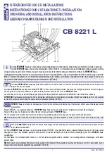
ISTRUZIONI PER USO ED INSTALLAZIONE
INSTRUCTIONS POUR L’UTILISATION ET L’INSTALLATION
OPERATING AND INSTALLATION INSTRUCTIONS
GEBRAUCHSANWEISUNGEN UND INSTALLATION

Die Firma 

FERPORT S.a.s.

steht nicht für falsche Verbindungen und/oder Verletzungen der Steuereinheiten ein und wird sie auf jeden Fall nicht

in der Garantie einbeziehen.

Die Firma 

FERPORT S.a.s.

gibt genau an, dass sie das Modell 

CB  8221  L

hat patentieren lassen. Dieselbe Steuereinheit und all ihre Teile werden

deswegen  auf  Grund  des  Gesetzes  geschützt.  Man  darf  kein  Teil  dieses  Handbuchs  ohne  die  schriftliche  Genehmigung  der  Firma 

FERPORT  S.a.s.

vervielfältigen.
Die  Anschlüsse  an  die  Steuereinheit  müssen  nur  von  Fachleuten  ausgeführt  werden,  nachdem  sie  die  obengenannten  Anweisungen  aufmerksam
gelesen haben.

NB:

Man braucht, einen allpoligen Schalter an die Steuereinheit mit mindestem Öffnungsabstand zwischen den Kontakten von 3 mm einzusetzen, der die

Steuereinheit vor der Instandhaltungsöffnung ausschaltet. (CEI 64-8)

La ditta 

FERPORT S.a.s.

non risponde per errati collegamenti e/o manomissioni delle centrali e tantomeno le riterrà in garanzia.

La ditta 

FERPORT S.a.s.

precisa di aver depositato il Mod. CB 8221 L. Il medesimo sarà quindi tutelata in tutte le sue parti a norma

di legge. Nessuna parte del contenuto di questo manuale può essere riprodotta senza autorizzazione scritta della 

FERPORT S.a.s.

I collegamenti alla centrale devono essere eseguiti solo da personale specializzato e dopo aver attentamente letto le istruzioni sopra riportate.

N.B.

: E’ richiesto l’inserimento di un interruttore onnipolare presso la centrale, con distanza di apertura minima dei contatti di 3 mm, per lo

spegnimento della stessa prima dell’apertura per manutenzione (CEI 64-8).

Rev. 001 07/03

I

D

F

GB

LOG

F1 F2

K7 K4

T1

K3

AP

J3

RX

LC

M5

M4

M6

K6

M1

M2 M3

K2K1 K5 K8

CB 8221 L

CB 8221 L

Summary of Contents for CB 8221 L

Page 1: ...ATING AND INSTALLATION INSTRUCTIONS GEBRAUCHSANWEISUNGEN UND INSTALLATION Die Firma FERPORT S a s steht nicht für falsche Verbindungen und oder Verletzungen der Steuereinheiten ein und wird sie auf jeden Fall nicht in der Garantie einbeziehen Die Firma FERPORT S a s gibt genau an dass sie das Modell CB 8221 L hat patentieren lassen Dieselbe Steuereinheit und all ihre Teile werden deswegen auf Grun...

Page 2: ...mer regolatore forza motore F1 Fusibile alimentazione motore 5 A 250 V F2 Fusibile alimentazione scheda 0 5 A 24 V LED A Se acceso con luce fissa indica cancello in movimento Se lampeggia velocemente indica cancello in attesa e controllo stato ingressi B FCA Motore 1 C FCC Motore 1 D FCA Motore 2 E FCC Motore 2 F STOP G FOTOCELLULE H APRE I CHIUDE 24V Led segnalazione presenza 24Vac 5V Led segnala...

Page 3: ...10 Ingresso aprertura pedonale N A 11 Ingresso di STOP N C 12 Comune 13 Ingresso fotocellula N C 14 Ingresso fine corsa di chiusura N C Motore 2 15 Ingresso fine corsa di apertura N C Motore 2 16 Comune 17 Ingresso fine corsa di chiusura N C Motore 1 18 Ingresso fine corsa di apertura N C Motore 1 MORSETTIERA M2 CH AP C CH AP C LAMP M1 M2 19 20 21 22 23 24 25 26 19 Contatto pulito lampeggiante 20 ...

Page 4: ...da un minimo di 120 V a un massimo di 230V Questa funzione viene attuata automaticamente dopo circa 3 secondi dalla partenza dei motori LED SEGNALAZIONE È possibile per constatare lo stato del cancello collegare un LED con in serie una resistenza da 1 KOHM Il led dovrà avere il Katodo terminale più corto al negativo morsetto 34 mentre la resistenza potrà essere montata indifferentemente sul morset...

Page 5: ...sere posto in OFF CONFIGURAZIONE DEI DIP 1 2 3 8 TIPO DI FUNZIONAMENTO A Passo passo APRE STOP CHIUDE senza richiusura automatica B Passo passo APRE STOP CHIUDE con richiusura automatica C Passo passo APRE CHIUDE senza richiusura automatica D Passo passo APRE CHIUDE con richiusura automatica E Semiautomatico durante l apertura non accetta altri impulsi fino a quando non richiude non ha la richiusu...

Page 6: ... programmato tramite il selettore o il radiocomando vedi POS 3 tempo di lavoro in chiusura anche in questo caso per far ripartire il cancello dopo il tempo di sosta dare 2 impulsi 3 e 4 in sequenza veloce N B il tempo di lavoro in apertura e chiusura nei cancelli con finecorsa dovrà essere superiore a 4 5 sec all intervento del finecorsa PROGRAMMAZIONE APERTURA PARZIALE CON SCHEDA SCHAP INSERITA D...

Page 7: ...omatique T1 Trimmer réglage force moteur F1 Fusible alimentation moteur 5 A 250 V F2 Fusible alimentation carte 0 5 A 24 V Témoins LED A Si allumé avec lumiére fixe la frille est en marche S il clignote rapidement la grille est en état d attente et le controle des entrées est actif B FCA Moteur 1 C FCC Moteur 1 D FCA Moteur 2 E FCC Moteur 2 F ARRET G FOTOCELLULES H AUVERTURE I FERMETURE 24V Led si...

Page 8: ...N A 11 Entrée ARRET N C 12 Commun 13 Entrée photocellule N C 14 Entrée fin de course fermeture N C Moteur 2 15 Entrée fin de course ouverture N C Moteur 2 16 Contact commun 17 Entrée fin de course fermeture N C Moteur 1 18 Entrée fin de course ouverture N C Moteur1 BOITE A BORNES M2 CH AP C CH AP C LAMP M1 M2 19 20 21 22 23 24 25 26 19 Contact sans interférence clignotant 20 Contact sans interfére...

Page 9: ...ette fonction se passe de maniére automatique aprés environ 3 secondes du démarrage des moteurs TEMOIN LED SEGNALISATION Il est possible de connecter en série un témoin Led é une résistance 1 KOHM ce qui permet de controler l état de fonctionnement de la grille La Cathode borne la plus courte du témoin Led sera réglée au pole négatif borne 34 tandis que la résistance pourra indifféremment etre con...

Page 10: ...URE ARRÊT FERMETURE avec réfermeture automatique C Pas à pas OUVERTURE FERMETURE sans réfermeture automatique D Pas à pas OUVERTURE FERMETURE avec réfermeture automatique E Semi automatique pendant l ouverture ce type de fonctionnement exclut les autres impulsions jusqu à la réfermeture Il est dépourvu de la fonction de réfermeture automatique En cas de réfermeture presser la touche FERMETURE F Se...

Page 11: ... la radiocommande cf POS 3 temps de travall ouverture POS 4 temps de résidence POS 6 temps de travall en fermeture Meme dans ce cas le redémarrage de la grille aprés le temps de résidence se produit en transmettant 2 impulsion 3e et 4e en séquence rapide NOTA Le temps de travail en ouverture et fermeture des grilles mulies de fins de course deit etre supérior de 4 5 sec lors de l activation du fin...

Page 12: ...0 5 A 24 V TECHNICAL SPECIFICATIONS V ac 220 10 Hz 50 60 HP 2 max G P IP55 Max PW supply box light 800W 24V 5V A B C D E F G H I ENGLISH LED A Lit gate moving Blinking gate in stand by mode and inputs status check B Engine FCA 1 C Engine FCC 1 D Engine FCA 2 E Engine FCC 2 F STOP G PHOTOCELLS H OPEN I CLOSE 24 V Led signalling presence 24Vac 5V Led signalling presence 5V ...

Page 13: ...pen income N A 11 STOP income N A 12 Common 13 Photocell income N C 14 Income End of stroke close N C Engine 2 15 Income end of stroke open N C Engine 2 16 Common 17 End of stroke income close N C Engine 1 18 End of stroke income open N C Engine 1 TERMINAL BLOCK M2 CH AP C CH AP C LAMP M1 M2 19 20 21 22 23 24 25 26 19 Blinker interference free contact 20 Blinker interference free contact 21 Engine...

Page 14: ... function is automatically operated about 3 seconds after the engines start up and designed to provide the maximum power STATUS LED In order to check the status of the gate a LED can be connected with a 1 KOhm resistor in series The LED s cathode short pin is to be connected to the negative end terminal 34 while the resistor can be mounted elther on terminal 33 or 34 ELECTRICAL LOCK RELEASE When t...

Page 15: ...Step step OPEN STOP CLOSE without automatic re close function B Step step OPEN STOP CLOSE whit automatic re close function C Step step OPEN CLOSE without automatic re close function D Step step OPEN CLOSE whit automatic re close function E Half automatic during the opening it will not accept other incoming signals until it has not closed it has no automatic re close function and in case sick funct...

Page 16: ... end of stroke and the pausing time is set by the selector or the remote control see pos 3 open time pos 4 pausing time pos 6 clousing time In this case the gate will be operated after the pause with 2 signals 3rd and 4th in quick seuqnce N B the opening and closing time in gates with limit clamp must be longer than 3 4 seconds when limit clamps operate HALF OPENING WITH SCHAP BOARD After having s...

Page 17: ... Motorleistungskraft F1 Schmelzsicherung für die Motorstromversorgung 5 A 250 V F2 Schmelzsicherung für die Kartestromversorgung 0 5 A 24 V SIGNAL LED A Wenn sie ständig leuchtet meldet sie die Bewegung des Tors Wenn sie schnell blinkt meldet sie den Pausezustand des Tors und die Zustandskontrolle der Eingänge B FCA Motor 1 C FCC Motor 1 D FCA Motor 2 D FCC Motor 2 F STOP G FTC H ÖFFNEN I SCHLIEßE...

Page 18: ...P Eingang N G 12 Gemeinsame Erdungseinheit 13 Photozelle Eingang N G 14 Eingang des Schließungsendschalters N G Motor 2 15 Eingang des Öffnungsendschalters N G Motor 2 16 Gemeinsame Erdungseinheit 17 Eingang des Schließungsendschalters N G Motor 1 18 Eingang des Öffnensendschalters N G Motor 1 KLEMMLEISTE M2 CH AP C CH AP C LAMP M1 M2 19 20 21 22 23 24 25 26 19 Kontakt des Blinkers nicht zur Erdun...

Page 19: ...imum von 230V Diese Funktion wird automatisch etwa 3 Sekunden nach dem Anlauf des Motors SIGNAL LED Um den zustand des Tors zu prüfen ist es möglich eine LED mit einem in Reihe geschalteten Wiederstand zu 1 KILOOOHM zu verbinden Die Kathode der LED ihr kurzer Anschluss soll an den Minus angeschlossen werden Klemmleiste 34 und sein Wiederstand kann sowohl an der Klemmleiste 33 als auch an der Klemm...

Page 20: ...eise ÖFFNEN STOP SCHLIEßEN ohne automatische Wiederschließung B Schrittweise ÖFFNEN STOP SCHLIEßEN mit automatischer Wiederschließung C Schrittweise ÖFFNEN SCHLIEßEN ohne automatische Wiederschließung D Schrittweise ÖFFNEN SCHLIEßEN mit automatischer Wiederschließung E Semiautomatisch während der Öffnung setzt sie keinen anderen Impuls bis zur Wiederschließung um Es ist keine automatische Wiedersc...

Page 21: ... Endschaltern bestimmt wird und dass die Betriebs und die Pausezeit mit dem Wählschalter oder mit dem Funksender programmiert werden s POS 3Arbeitszeit bei der Schließung um das Tor am Ende der Pausezeit in Gang zu setzen geben Sie auch in diesem Fall 2 Impulse 3 und 4 schnell nacheinander NB die Betriebsszeit bei der Schließung und bei der Öffnung für Tore mit Endschalter sollte 4 5 Sekunden läng...

Page 22: ...22 NOTE ...

Page 23: ...23 NOTE ...

Page 24: ...24 Via Chienti 10 20052 Monza MI Italy Tel 39 039 734095 Fax 39 039 734951 web site www ferport it e mail ferport ferport it STUDIO GRAFICO IMMAGINE tel 030 9913938 ...

Reviews: