background image

KEEP THESE INSTRUCTIONS WITH THE 

INSTALLED VALVE FOR FUTURE REFERENCE


WARNING

•  Read and understand all instructions before attempting to install any Victaulic products.
•  Always verify that the piping system has been completely depressurized and drained 

immediately prior to installation, removal, adjustment, or maintenance of any Victaulic 
products.

•  Wear safety glasses, hardhat, and foot protection.
Failure to follow these instructions could result in death or serious  personal injury and property 
damage.


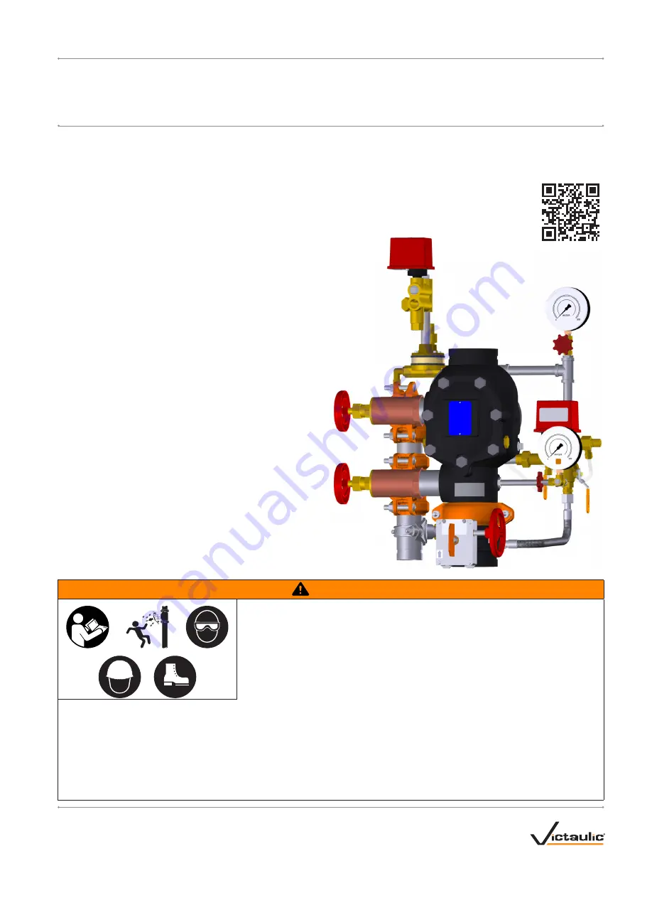
•  Series 769N FireLock NXT

 Deluge Valves shall be used only in fire protection systems that are designed and installed in accordance with 

current, applicable National Fire Protection Association (NFPA 13, 13D, 13R, etc.) standards, or equivalent standards, and in accordance 
with applicable building and fire codes. These standards and codes contain important information regarding protection of systems from 
freezing temperatures, corrosion, mechanical damage, etc.

•  These installation instructions are intended for an experienced, trained installer. The installer shall understand the use of this product and 

why it was specified for the particular application.

•  The installer shall understand common industry safety standards and potential consequences of improper product installation.
Failure to follow installation requirements and local and national codes and standards could compromise system integrity or cause system 
failure, resulting in death or serious personal injury and property damage.

Scan QR Code for Access to Videos 

and Additional Publications

I-769N.Deluge

INSTALLATION, MAINTENANCE, AND TESTING MANUAL

Series 769N FireLock NXT

 Deluge Valve 

Pneumatic (Dry Pilot) Release, Hydraulic (Wet Pilot) Release, and Electric Release Systems

I-769N.Deluge

REV_F

Summary of Contents for 769N FireLock NXT Series

Page 1: ...pplicable building and fire codes These standards and codes contain important information regarding protection of systems from freezing temperatures corrosion mechanical damage etc These installation instructions are intended for an experienced trained installer The installer shall understand the use of this product and why it was specified for the particular application The installer shall unders...

Page 2: ...low fill ball valve open may allow system pressure to drop resulting in valve operation in the event of a system leak Step P5e Open the charge line ball valve Allow water to flow through the auto drain tube Step P5f Pull up on the auto drain sleeve FOR ELECTRIC RELEASE SYSTEMS Step E5a Confirm that the solenoid valve is closed de energized Step E5b Confirm that water is not flowing through the sol...

Page 3: ...be performed 2 Open the water supply main drain valve fully to flush the water supply of any contaminants 3 Close the water supply main drain valve 4 Open the alarm test ball valve Confirm that mechanical and electrical alarms are activated and that remote monitoring stations if provided receive an alarm signal 5 Close the alarm test ball valve after verifying proper operation of all alarms 6 Push...

Page 4: ...n death or serious personal injury and property damage if instructions are not followed CAUTION The use of the word CAUTION identifies possible hazards or unsafe practices that could result in personal injury and product or property damage if instructions are not followed NOTICE The use of the word NOTICE identifies special instructions that are important but not related to hazards INSTALLER SAFET...

Page 5: ... psi 10 kPa 0 1 Bar leakage in 24 hours 6 Supply water to the system Supply pressure to the charge line by providing an uninterrupted source of water from upstream of the main control valve When an uninterrupted water flow alarm is required Victaulic recommends the use of a low pressure alarm installed on the charge line downstream of the priming manifold assembly 7 Pitch the water supply piping P...

Page 6: ...ot enter the trim Failure to follow these instructions could cause improper valve operation resulting in personal injury and property damage 3 Install the valve assembly into the riser with two Victaulic rigid couplings Refer to the instructions supplied with the coupling for complete installation requirements SERIES 769N FIRELOCK NXT DELUGE VALVES SHALL BE INSTALLED ONLY IN THE VERTICAL POSITION ...

Page 7: ...mbly is ordered Nominal Size inches or mm Dimensions inches mm Approx Weight Each lbs kg A A1 B C D D1 E F G H K Without Trim With Trim 1 9 00 16 37 33 00 8 75 14 25 9 00 9 25 3 25 10 25 22 75 5 50 16 7 43 0 228 60 415 80 838 222 362 229 235 83 260 578 140 7 6 19 5 2 9 00 13 83 33 00 8 75 15 50 9 00 9 25 3 25 10 25 22 75 5 50 17 0 43 0 228 60 351 28 838 222 394 229 235 83 260 578 140 7 7 19 5 2 12...

Page 8: ... 7 15 16 11 6 5 2 3 14 13 12 1 4 Item Description 1 Series 769N FireLock NXT Deluge Valve 2 FireLock Rigid Coupling 3 Water Supply Main Control Valve 4 Drip Cup 5 Water Supply Main Drain Valve Flow Test 6 System Main Drain Valve 7 Air Manifold 8 Series 776 Low Pressure Actuator Item Description 9 Charge Line Pressure Gauge Gauge Valve Assembly 10 Series 755 Manual Pull Station 11 Series 760 Water ...

Page 9: ...fy components that are optional equipment 9 8 7 13 10 6 5 2 3 12 11 4 1 Item Description 1 Series 769N FireLock NXT Deluge Valve 2 FireLock Rigid Coupling 3 Water Supply Main Control Valve 4 Drip Cup 5 Water Supply Main Drain Valve Flow Test 6 System Main Drain Valve 7 Charge Line Pressure Gauge Gauge Valve Assembly Item Description 8 Series 755 Manual Pull Station 9 Series 760 Water Motor Alarm A...

Page 10: ...nal equipment 9 8 7 14 10 6 5 2 3 13 12 11 4 1 Item Description 1 Series 769N FireLock NXT Deluge Valve 2 FireLock Rigid Coupling 3 Water Supply Main Control Valve 4 Drip Cup 5 Water Supply Main Drain Valve Flow Test 6 System Main Drain Valve 7 24 VDC Normally Closed Solenoid Valve Item Description 8 Charge Line Pressure Gauge Gauge Valve Assembly 9 Series 755 Manual Pull Station 10 Series 760 Wat...

Page 11: ... Assembly Bolt 8 Clapper Spring 9 Clapper Shaft 10 Clapper Shaft Bushing and O Ring Qty 2 Item Description 11 Cover Plate 12 Cover Plate Gasket 13 Cover Plate Bolts 14 Latch 15 Latch Spring 16 Latch Spring Bushing and O Ring Qty 2 17 Diaphragm 18 Diaphragm Cover 19 Diaphragm Cover Cap Screws Qty 8 20 Latch Shaft The 1 inch 48 3 mm and 2 inch 60 3 mm valve sizes contain washers under the heads of t...

Page 12: ...ve with dry pilot trim it is not necessary to install the Victaulic Series 757 Regulated Air Maintenance Trim Assembly AMTA In this case the air line of the compressor connects to the trim at the fitting where the Series 757 Regulated AMTA is installed normally refer to the applicable trim drawing If the compressor is not equipped with a pressure switch the Series 757P Air Maintenance Trim Assembl...

Page 13: ...00 300 400 500 1000 1 2 inch 48 3 60 3 mm Valve Sizes LENGTH OF PIPE FEET MAXIMUM PILOT LINE HEIGHT FEET 300 psi 280 psi 260 psi 240 psi 220 psi 200 psi 140 psi 120 psi 100 psi 80 psi 60 psi 40 psi 20 psi 180 psi 160 psi 280 psi 260 psi 240 psi 220 psi 200 psi 180 psi 160 psi 140 psi 120 psi 100 psi 80 psi 60 psi 40 psi 20 psi 300 psi 0 20 40 60 80 100 120 140 10 25 50 100 200 300 400 500 1000 2 3...

Page 14: ...00 0 20 40 60 80 100 120 140 300 psi 280 psi 260 psi 240 psi 220 psi 200 psi 180 psi 160 psi 140 psi 120 psi 100 psi 80 psi 60 psi 40 psi 20 psi 4 inch 114 3 mm Valve Size LENGTH OF PIPE FEET MAXIMUM PILOT LINE HEIGHT FEET 0 50 100 150 200 250 10 25 50 100 200 300 400 500 1000 300 psi 280 psi 260 psi 240 psi 220 psi 200 psi 180 psi 160 psi 140 psi 120 psi 100 psi 80 psi 60 psi 40 psi 20 psi 6 inch...

Page 15: ...or specific equivalent lengths heights are based on 1 2 inch 21 3 mm Schedule 40 pipe and a 1 2 inch 21 3 mm sprinkler 0 50 100 150 250 300 200 10 25 50 100 200 300 400 500 1000 225 psi 200 psi 180 psi 160 psi 140 psi 120 psi 100 psi 80 psi 60 psi 40 psi 20 psi 8 inch 219 1 mm Valve Size LENGTH OF PIPE FEET MAXIMUM PILOT LINE HEIGHT FEET I 769N Deluge_15 REV_F ...

Page 16: ...I 769N Deluge Series 769N FireLock NXT Deluge Valve Installation Maintenance and Testing Manual SECTION I Initial System Setup I 769N Deluge_16 REV_F ...

Page 17: ...LEASE SYSTEMS Step P5a Charge the dry pilot release system with air by turning on the compressor or by opening the fast fill ball valve on the AMTA Charge the dry pilot release system to 13psi 90kPa 0 9Bar minimum Refer to the Air Supply Requirements section Step P5b When the system reaches approximately 10psi 69 kPa 0 7Bar and no additional moisture is being released from the Auto Vent pull up on...

Page 18: ... 12 Notify the authority having jurisdiction remote station alarm monitors and those in the affected area that the system is in service Valve Normal Operating Position Water Supply Main Control Valve Open Water Supply Main Drain Valve Closed System Main Drain Valve Closed Charge Line Ball Valve of the Priming Manifold Assembly Open Alarm Test Ball Valve of the Priming Manifold Assembly Closed Slow...

Page 19: ...I 769N Deluge Series 769N FireLock NXT Deluge Valve Installation Maintenance and Testing Manual This page intentionally left blank I 769N Deluge_19 REV_F ...

Page 20: ...I 769N Deluge Series 769N FireLock NXT Deluge Valve Installation Maintenance and Testing Manual SECTION II Resetting the System I 769N Deluge_20 REV_F ...

Page 21: ...arge line ball valve by placing it in the closed position Step 2 Close the water supply main control valve Step 2a Isolate the air supply to the system Step 3 Open the system main drain valve Confirm that the system is drained Step 3a Push in the ball drip plunger to release pressure Step 3b The cover plate shall be removed to verify that the clapper is resting on the seat in the closed position F...

Page 22: ...ments The authority having jurisdiction in the area may require these inspections on a more frequent basis Verify these requirements by contacting the authority having jurisdiction in the affected area and always refer to the instructions in this manual for additional inspection and testing requirements The frequency of inspections shall be increased in the presence of contaminated water supplies ...

Page 23: ...e of the Priming Manifold Assembly Open Alarm Test Ball Valve of the Priming Manifold Assembly Closed Slow Fill Ball Valve of the Victaulic AMTA if applicable Open Fast Fill Ball Valve of the Victaulic AMTA if applicable Closed QUARTERLY INSPECTION Refer to NFPA 25 FM Datasheets or any applicable local requirements to perform quarterly inspections The authority having jurisdiction in the area may ...

Page 24: ...tions in this manual for additional inspection and testing requirements The frequency of inspections shall be increased in the presence of contaminated water supplies corrosive scaling water supplies and corrosive atmospheres Any activities that require taking the valve out of service may eliminate the fire protection provided A fire patrol is strongly recommended for the affected areas Before ser...

Page 25: ...lve fully to flush the water supply of any contaminants 6 While the water supply main drain valve is fully open record the water supply pressure from the water supply gauge as the r esidual pressure 7 Close the water supply main drain valve slowly 8 Record the water pressure established after closing the water supply main drain valve 9 Compare the residual pressure reading to the residual pressure...

Page 26: ...ush the water supply of any contaminants 3 Close the water supply main drain valve 4 Open the alarm test ball valve Confirm that mechanical and electrical alarms are activated and that remote monitoring stations if provided receive an alarm signal 5 Close the alarm test ball valve after verifying proper operation of all alarms 6 Push in the ball drip plunger on the alarm manifold assembly to verif...

Page 27: ... system pressure When the normal system air pressure is reached close the fast fill ball valve on the AMTA Open the slow fill ball valve on the AMTA 7 Open the water supply main drain valve CAUTION Take precautions when opening the water supply main control valve since water will flow from all open system valves Failure to follow this instruction could result in property damage 8 Open the water su...

Page 28: ...n drain valve 7 Trip the valve by doing one of the following a Open energize the solenoid valve b Relieve pressure from the pilot line c Open the manual pull station valve 8 Confirm that the charge line s pressure drops to zero and that water is flowing through the auto drain to the drip cup 9 Close the water supply main control valve fully 10 Close the remote system test valve inspector s test co...

Page 29: ...id valve b Relieve pressure from the pilot line c Open the manual pull station valve 6 Record the following 6a The time between opening the remote system test valve inspector s test connection and operation of the deluge valve 6b FOR PNEUMATIC DRY PILOT RELEASE SYSTEMS System air pressure when the valve operated 6c The time between opening the remote system test valve inspector s test connection t...

Page 30: ...ctions on a more frequent basis Verify these requirements by contacting the authority having jurisdiction in the affected area and always refer to the instructions in this manual for additional inspection and testing requirements The frequency of inspections shall be increased in the presence of contaminated water supplies corrosive scaling water supplies and corrosive atmospheres Any activities t...

Page 31: ...rained completely before the cover plate bolts are removed Failure to follow this instruction could result in death or serious personal injury and property damage 11 After all pressure is released from the system loosen the cover plate bolts slowly NOTE DO NOT remove any cover plate bolts until all cover plate bolts are loosened 12 Remove all cover plate bolts along with the cover plate and cover ...

Page 32: ...r operating condition To ensure proper system operation refer to NFPA 25 FM Datasheets or any applicable local requirements for valve inspection requirements The authority having jurisdiction in the area may require these inspections on a more frequent basis Verify these requirements by contacting the authority having jurisdiction in the affected area and always refer to the instructions in this m...

Page 33: ...AUTION Use only Victaulic supplied replacement parts Failure to follow this instruction could cause improper valve operation resulting in property damage 6 Pry the clapper seal along with the seal ring out of the clapper Inspect the clapper seal If the clapper seal is torn or worn replace it with a new Victaulic supplied clapper seal If replacing the clapper seal assembly with a new assembly skip ...

Page 34: ...BLY BOLT BOLT SEAL TORQUES Nominal Size inches or mm Required Torque inch lbs N m 1 1 2 40 5 2 40 5 2 1 2 90 10 76 1mm 90 10 3 90 10 4 110 12 165 1mm 160 18 6 160 18 8 160 18 12 Replace the cover plate by following the Installing the Cover Plate Gasket and Cover Plate section 13 Place the system back in service by following the Resetting the System section REMOVING AND REPLACING THE CLAPPER ASSEMB...

Page 35: ... shaft bushings into the valve body until hand tight 9b Tighten the clapper shaft bushings until metal to metal contact occurs with the valve body DO NOT exceed 10 ft lbs 14 N m of torque on the clapper shaft bushings 9c Check the clapper for freedom of movement 10 Replace the cover plate by following the Installing the Cover Plate Gasket and Cover Plate section 11 Place the system back in service...

Page 36: ...41 2 1 2 60 81 76 1mm 60 81 3 60 81 4 100 136 165 1mm 115 156 6 115 156 8 100 136 6 Place the system back in service by following the Resetting the System section REMOVING AND REPLACING THE DIAPHRAGM 1 Remove the system from service by following steps 1 10 of the Required Internal Inspection section 2 Break the unions that connect the trim to the diaphragm cover Refer to the applicable trim drawin...

Page 37: ...ction section 2 Remove the existing cartridge from the air manifold dry pilot release systems and priming manifold assemblies shown above Rinse the cartridges to remove any deposits 3 Install the corresponding cartridge into the air manifold and priming manifold assemblies NOTE The face of the air manifold cartridge is stamped AM and the face of the priming manifold cartridge is stamped PM These c...

Page 38: ...I 769N Deluge Series 769N FireLock NXT Deluge Valve Installation Maintenance and Testing Manual SECTION VII Troubleshooting I 769N Deluge_38 REV_F ...

Page 39: ...riction in the piping between the air manifold and the auto vent of the Series 776 Low Pressure Actuator Remove the air feed nipple and remove any debris Clean the restrictor and strainer in the air manifold Verify that no debris has built up in the air manifold ports that could be restricting airflow When the AutoVent Sleeve of the Series 776 Low Pressure Actuator is pulled up the screw does not ...

Page 40: ...T S 769 mit elektrischer Anregung I 769N Deluge INSTALLATION MAINTENANCE AND TESTING MANUAL Series 769N FireLock NXT Deluge Valve Pneumatic Dry Pilot Release Hydraulic Wet Pilot Release and Electric Release Systems For complete contact information visit victaulic com I 769N Deluge 9241 REV F UPDATED 01 2019 Z000769ND0 VICTAULIC AND FIRELOCK NXT ARE REGISTERED TRADEMARKS OR TRADEMARKS OF VICTAULIC ...

Reviews: