


1
IMPO
RTAN
T:
IMPO
RTAN
T:
Go to www
.extron.com f
or the complete
user guide
, installation instructions,
and
specifications bef
ore connecting the
product to the po
wer sour
ce.
Annotator 401 • Setup Guide
The Extron Annotator 401 Annotation Graphics Processor is a scaling product that allows a presenter to draw, point, or type on
live video or computer source content using a touchpanel, mouse, or keyboard.
This setup guide allows you to easily and quickly set up and configure your Annotator 401 using step-by-step instructions. It
covers performing basic operations using the front panel controls.
NOTE:
For full installation, configuration, menus, and operation details - including using Extron Simple Instruction Set (SIS
TM
)
commands and Product Configuration Software (PCS), see the
Annotator 401 User Guide
at
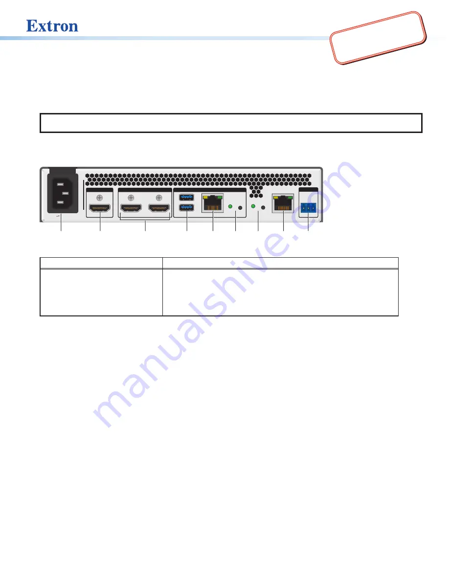
Rear Panel Features
ANNOTATOR 401
ANNOTATION GRAPHICS PROCESSOR
CONFIG
MENU
NEXT
500 mA
ADJUST
ANNOTATOR 401
100-240V --A MAX 50-60Hz
LAN
USB EXT
RESET
PAIR
250 mA
1
2
3
REMOTE
DEVICES
OUTPUTS
INPUT
HDMI
1
HDMI
2
HDMI
RS-232
Tx Rx G
A B
C
D
E
A
B
D
E
C
F
G
H
I
Figure 1.
Rear Panel Features
Power and video input connections
Outputs and control connections
A
AC power connector
B
HDMI input connector
C
HDMI output connectors (2)
D
USB-A connectors (2)
E
USB EXT RJ-45 connector
F
Pairing button and Status LED
G
Reset button and LED
H
RJ-45 LAN connector
I
RS-232 3-pole captive screw
connector
Installation
Mounting and Cabling
Step 1 — Mounting (optional)
a.
Turn off or disconnect all equipment power sources.
b.
Place the Annotator 401 on top of a flat surface using the provided rubber feet, mount it under a table using an optional kit
for under desk mounting, or attach it to a rack shelf using an optional rack shelf-mounting kit (available at
).
Step 2 — Connecting input
Connect digital video source to the HDMI input connector (see figure 1,
B
above)
.
Step 3 — Connecting outputs
Connect suitable video displays to one or both of the two HDMI output connectors (
C
).
Step 4 — Connecting control devices
a.
For control through Ethernet, connect a LAN or WAN to the RJ-45 connector (
H
). The default IP address is 192.168.254.254.
The default subnet mask is 255.255.255.0.
b.
For serial RS-232 control, connect a host device to the 3-pole captive screw connector (
I
). The default baud rate is 9600.
c.
For control through USB, connect a host device to the front panel USB-C port (see
Step 5 — Connecting user interface devices or touchpanels
Connect user interface devices (such as a mouse, keyboard, or touchpanels) to the Annotator 401 using either of the rear panel
USB ports (see figure 1,
D
). Alternatively the front panel USB port (see
) can also be used to connect a user interface
device.
1


