


User Manual
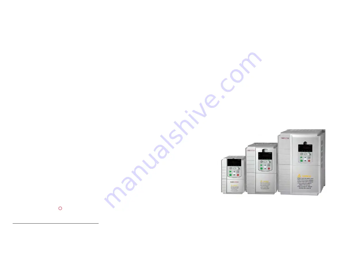
EM12 Series Frequency Inverter
EM
1
2 S
er
ie
s F
re
q
u
en
cy
In
ve
rt
er
EMHEATER
China
EM
Technology
Limited
China EM Technology Limited
Address:
No.80, Baomin 2 road, Xixiang, Bao'an District,Shenzhen ,China
Phone:
86-0755-29985851
Fax:
86-0755-29970305
Zip code: 518101
Website : Http://www.emheater.com
EMHEATER
R
Summary of Contents for EM12 Series
Page 5: ......


