MN05405001E
1
español
english
français
deutsch
italiano
Operating Instructions
Timers
E5-248-C1420
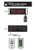
FRONT PANEL
The key below each digit sets the Set Time on the Subsidiary Display. The red reset
key resets the unit to zero when timing up or to the Set Time when timing down.
Direction of timing is programmable. There are several annunciators as follows:
• PROG appears in programming mode
•
and
indicate direction of
timing
• Various segments of the suite of mode
annunciators indicate the current mode
and status at a point in time
• Relay Symbol. Indicates whether relay
contacts are open or closed
• LEVEL EDGE RETRIG indicates
triggering mode.
• HRS MIN SEC together with the decimal
point position indicates which timing
range is selected.
1 2 3 4 5 6 7
DESCRIPTION
This programmable timer has a two line black on silver LCD readout with the timing on
the Main Display and the Set Time on the Subsidiary Display. A wide range of modes
can be selected in programming.
CONNECTIONS
Typical Installation Wiring
Neutral
Relay
Short to inhibit
keyboard
Live
Timer Input
External Reset
Main Display
Reset
Digit 5
Digit 1
Subsidiary Display
S
1
Common for terminals 2 + 3
2
Timing input.
Programmable
to level or edge
triggered
These inputs can
be 12-240V AC or
DC. For DC input
the polarity is
unimported
3
Reset input
4/5 Voltage free relay contacts.
Programmable to NO or NC
6/7 Connect together to disable front
panel keys