EBOT MAZE
EBOT MAZE
MANUAL GUIDE
MANUAL GUIDE
VARIANTS:
EBOT STANDARD
> Line follower
> Maze Solver
> Sumo fight
EBOT MAZE
> with Ultrasonic sensor
EBOT SUMO
> with Ultrasonic sensor and bumper accessory
EBOT SOCCER
> with Bluetooth Shield
EBOT with GRIPPER
> with Gripper arm
> with PS2 Controller
EBOT with EGRA
> with EGRA (Robotic Arm)
> with PS2 Controller
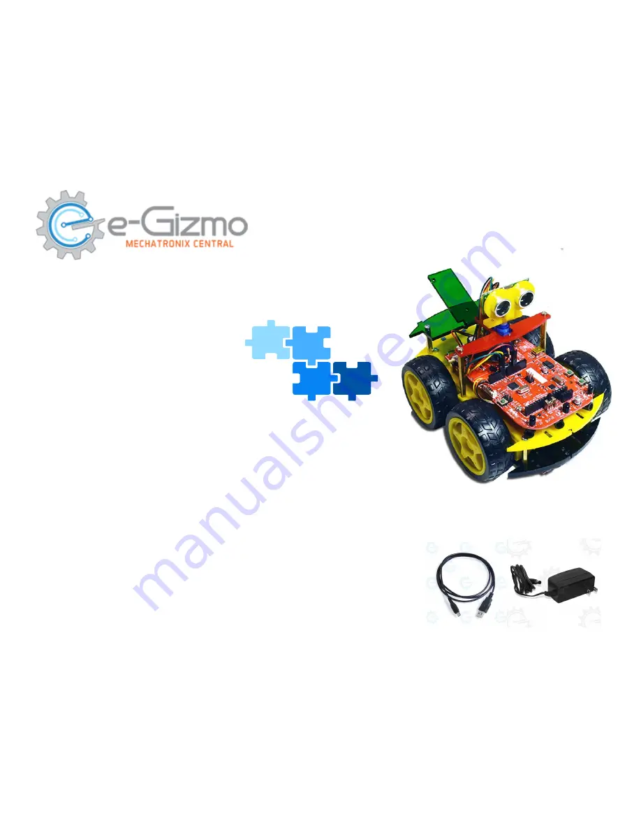
Included:
- USB Cable Type A to mini B
- 9V 1A adaptor
Summary of Contents for EBOT MAZE
Page 4: ...PBOT 2018 BOARD PBOT 2018 BOARD MAJOR PARTS ...
Page 7: ...Connect the EBOT to PC USB Connector USB Cable Open Arduino IDE ...
Page 9: ...Turn your Ebot Maze for More Functions like EBOT STANDARD Go to Next Page ...
Page 23: ...SERVO CONNECTION Servo labels 1 4 Servo connectors from P3 P6 Servo Supply J2 ...