


??
IMPORTANT INFORMATION
IMPORTANT INFORMATION
??
KEEP FOR OPERATOR
KEEP FOR OPERATOR
??
IMPORTANT INFORMATION
IMPORTANT INFORMATION
?
OPERATOR AND SERVICE MANUAL
OM/SM-AH-CE
Part Number 128416
INTERNATIONAL
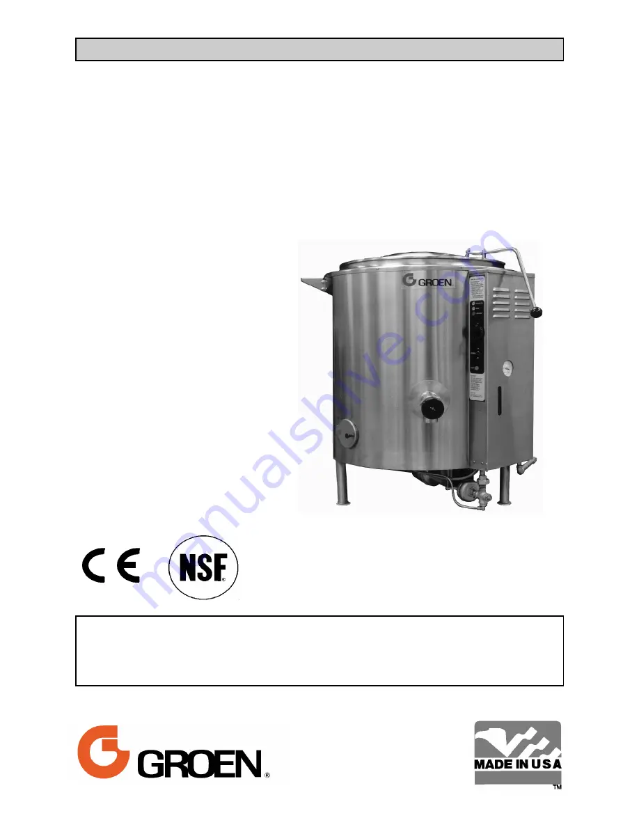
Model:
AH-CE Mark
Steam Jacketed Kettle
Self-contained
Stainless Steel
Gas Heated
Floor Mounted
Stationary
KEEP THIS MANUAL WITH KETTLE DOCUMENTS. OPERATORS AND
TECHNICIANS SHOULD READ, UNDERSTAND AND FOLLOW WARNINGS AND
INSTRUCTIONS IN THIS MANUAL (THE SERVICE MANUAL AND THE OPERATOR
SECTIONS)
Information contained in this document is
known to be current and accurate at the time
of printing/creation. Unified Brands recom-
mends referencing our product line websites,
unifiedbrands.net, for the most updated
product information and specifications.
Summary of Contents for GROEN AH-20
Page 23: ...OM SM AH CE 23 ...
Page 24: ...OM SM AH CE 24 Parts Lists ...


