Description
The Model 740, 741, and 743 SC Series LED Keypads are the
industry's finest sub-control keypads with integrated access control
capabilities. The keypads operate as a stand-alone system that
provides arming, disarming, local alarm notification, Wiegand
input, and access control. When connected to the LX-Bus™ of an
XR200 or XR200-485, the keypad's local zones are supervised
for alarm annunciation.
Each keypad provides three local zones for burglary and one zone
for non-powered fire devices or a panic button. Also provided are
a 2-button Panic key, three system status LEDs, three armed
status LEDs, four zone LEDs, a backlit keyboard with easy to read
lettering, and an internal speaker/siren.
The 741 and 743 keypads include a standby battery backup
circuit, a Wiegand input, and one Form-C relay. Additionally, the
743 includes an internal Wiegand proximity reader.
Zone Supervision
The keypad can only be connected to an LX-Bus for zone
supervision then reports the open, normal, or short condition of
the local keypad zones to the panel. The keypads programmed
address is used as a starting point to report the conditions of local
zone 1 to the corresponding LX-Bus panel zone (Ex. address 75
= LX-Bus zone 175). Local zone 2, 3, and 4 conditions are
reported on the next three panel zones (Ex. zone 2 = 176, zone
3 = 177, zone 4 = 178). Additionally, the keypads may be
programmed to report an alarm from any of the four zones on only
one LX-Bus zone. The corresponding LX-Bus panel zones must
be programmed and then armed to create an alarm when the local
zone reports a
short to the LX-Bus. A normal zone condition is
continuously sent to the LX-Bus when the keypad is disarmed and
when a zone is automatically swinger bypassed (3 trips during the
armed period).
Internal Speaker/Siren
When an alarm occurs, the internal speaker can be programmed
to emit loud and distinct burglary or fire siren tones. Also, the
keypads emit tones for key presses, entry
delay, system alerts, and zone monitor.
After the user performs a successful
keypad operation, such as disarming the
system, the speaker emits a 1/2 second
tone. If the operation is not successful,
the speaker emits four short tones. This
alerts the user to perform the function again.
Bell Circuit
A switch ground circuit, rated for 500mA, is provided to switch
power for alarm bells or horns. This output turns on steady for
burglary alarms and temporal 3 cadence for fire alarm.
Form C Relay
The 741 and 743 keypads provide one internal Form C (SPDT)
relay. This relay may be used for a variety of functions based on
programming. It may be used for:
•
Access Control - connect to door strikes or magnetic locks.
•
Alarm Relay - connect to an external annunciator.
•
Sensor Reset - connect to power of 4-wire smoke detector.
The Form C relay draws up to 30mA of current and its contacts are
rated for 1 Amp at 24 VDC.
LT-0393 (7/98)
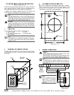
INSTALLATION/PROGRAMMING
740, 741, and 743 SC Series LED Keypads
2841 E. Industrial Drive Springfield, MO 65802-6310 800-641-4282
Wiegand Input
A Wiegand style card reader may be attached to the 741 and 743
SC Series keypads. Connect Black power wire from the reader in
parallel to the black ground wire of the keypad. Connect the White
data wire from the reader (Data 1) to the White wire on the Output/
Reader harness. Connect the Green data wire from the reader
(Data 0) to the Green/White wire on the Output/Reader harness.
Below are the specifications for individual readers:
MP-5365 MiniProx® Proximity Reader -
60mA at 12VDC
PR-5355 ProxPro® Proximity Reader -
60mA at 12VDC
TL-5395 ThinLine II™ Switchplate Reader - 60mA at 12VDC
580 Magnetic Stripe Card Reader -
50mA at 12VDC
2-Button Panic Keys
The Panic key function of the 740, 741, and 743 keypads allow
users to send Panic or Fire reports to the supervising alarm panel.
The user must press and hold the two SELECT keys for two
seconds until a beep from the keypad is heard. At the beep, the
keypad simulates a short on zone 4. Zone 4 programming
determines whether the keypad sends a Panic report or a Fire
report.
The Panic key function must be programmed if the Panic keys are
to be used. See the "Programming the keypad" section for
instructions. Cut the icon label for the appropriate function and
install the icon label below the top row of Select keys.
Main DC Power
The SC Series keypads require an external 12 VDC power source
to operate. The DC power source must be capable of supporting
each keypad based on the following chart. Additional current
capacity is required when a backup battery is connected.
Battery Backup
When using the 741 or 743 keypads, the Red/Black wire provides
a maximum 200mA output to charge a backup battery. The 741
and 743 include 14" battery leads for connection to a maximum
4Ah battery. The Red/Black wire on the 740
does not provide any
voltage output.
The battery backup output voltage varies based on the Main DC
input voltage as shown below.
Panic key label placement
Labels
show
icons
only
Top
row
SELECT
keys
A
BC
D
E
F
G H I
J K L
VW X
MN O
P
Q
R
STU
Y Z
COMMAND
SPECIAL
STAY
INSTANT
BYPASS
CODE
9
0
1
2
3
4
5
6
7
8
1
2 3 4
INSTANT
STAY
ARMED
TRBL
POWER
READY
Cut
here
for
Fire
Panic
▼
Cut
here
for
Police
Panic
▼
Main DC Input
Battery Backup Output
16 - 18 VDC
13.8 VDC regulated
15 VDC
13.5 VDC
14 VDC
12.5 VDC
13 VDC
11.5 VDC
Model
Voltage
Current
Normal
Alarm
Battery Backup
740
8 to 18 VDC
50 mA
100 mA
N/A
741
8 to 18 VDC
50 mA
130 mA
200 mA
743
8 to 18 VDC
70 mA
160 mA
200 mA