background image

1

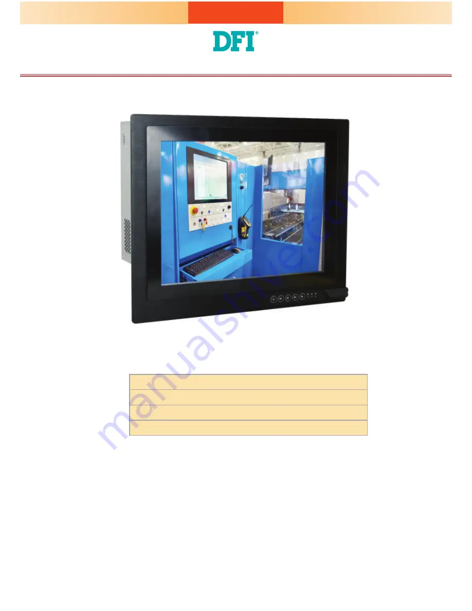
TPC150-SD Installation Guide

Package Contents

• One 15" Touch Panel PC

• One sheet of Poron foam

• 1 DVD disk includes:

   - Manual

DFI reserves the right to change the speci

fi

 cations at any time prior to 

the product's release. For the latest revision and more details of the 

installation procedure, please refer to the user's manual on the website.

www.d

fi

 .com

Summary of Contents for TPC150-SD

Page 1: ... sheet of Poron foam 1 DVD disk includes Manual DFI reserves the right to change the specifications at any time prior to the product s release For the latest revision and more details of the installation procedure please refer to the user s manual on the website www dfi com ...

Page 2: ...2 Top Panel Top View AC Power Socket LAN1 LAN2 Power Switch USB 3 0 Ports DP Port DVI D Port VGA Port PS 2 Keyboard Mouse Ports Expansion Slots COM Port RS232 USB 2 0 Ports ...

Page 3: ...s and cables 3 The 6 mounting screws on the bottom of the system are used to secure the cover to the chassis Remove these screws and put them in a safe place for later use SODIMM socket Mini PCIe socket 4 Lift the cover up to open the system 5 The Mini PCIe and the SODIMM sockets are readily accessible after removing the chassis cover Mounting screw ...

Page 4: ...e mounting holes of the SATA drive with the mounting holes on the HDD bracket and then use the provided mounting screws to secure the drive in place Mounting screws The system can accomondate two SATA drives Please use the following procedure to install SATA drives into the system HDD bracket SATA drive Mounting screw SATA drive bay HDD bracket Bracket screw ...

Page 5: ...ay and then use the provided mounting screws to secure the drive in place 4 Connect one end to the SATA data connector of the SATA drive and the other end to the SATA data port on the system board Connect the SATA power connector from the PSU to the SATA power connector Mounting screw Mounting screw SATA data port SATA data connector SATA power connector ...

Page 6: ...nector of the PCIe card with the key in the connector on the system board and use the provided mounting screws to secure the card on the system board Mini PCIe card Mounting screw Note The Mini PCIe socket supports PCIe and SATA signals and can accommodate common mobile broadband and storage modules For jumper settings on switching the signal betwen SATA and PCIe refer to Board Layout and Jumper S...

Page 7: ...nsion slots The riser card DFI model T100 2E provides 2 x PCIe Gen3 x8 expansion slots whereas the riser card DFI model X100 2P1M provides two PCI and one Mini PCIe slots 1 Remove the slot plate and bracket by removing the screws on the front chassis 2 Insert the expansion card into the PCIe slot on the riser card Ensure the card is properly seated into the slot Installing a PCIe Expansion Card PC...

Page 8: ...8 Front View 3 Install the bracket to secure the PCIe card in place ...

Page 9: ...ts Bracket screws 1 Select a place on the wall where you will mount the Panel PC 2 Use the provided mounting screws to attach VESA mount bracket 1 to the wall Mounting Options VESA mount VESA mount bracket 1 VESA mount bracket 2 VESA mount bracket 1 Mounting screw ...

Page 10: ...bracket 2 to the rear of the Panel PC 4 Slide the Panel PC to VESA mount bracket 1 to attach the two brackets with the hooks Then tighten the screw to secure the assembly in place Screw VESA mount bracket 2 Hooks Mounting screw Mounting screw ...

Page 11: ...an be fitted into the panel properly 3 Insert the Panel PC from the outside surface of the panel into the mounting hole until it is properly fitted against the panel 4 Position the mounting clamps along the rear edges of the Panel PC and insert them into the slits around the Panel PC Panel mount The panel mounting kit includes the following 6 mounting clamps 132 20 210 50 Panel Mounting hole 383 3...

Page 12: ... secured diagonally prior to mounting the rest of the clamps Tighten the clamp s screw using an electric screwdriver by pressing the white plastic cap onto the back of the panel The illustration below shows that all clamps are properly mounted Slit for mounting the clamp Mounting clamp White plastic cap ...

Page 13: ... JP8 JP1 JP2 SPI Flash BIOS JP1 JP2 JP7 JP8 JP6 Digital I O Digital I O Power 1 2 1112 Front Panel 1 Auto Power on Select JP5 1 System Fan 1 1 Clear CMOS Data JP4 1 Backlight Power Select JP3 1 System Fan 2 S PDIF 1 1 2 5 6 SMBus 1 CPU Fan ASMedia ASM1442 Standby Power LED 8 3 4 2 5 3 3 3 Auto Power on Select JP5 Power on via power button default 1 2 On Power on via AC power 2 3 On Mini PCIe Signa...

Reviews: