

G-POS Series
Quick Installation Guide V2.0
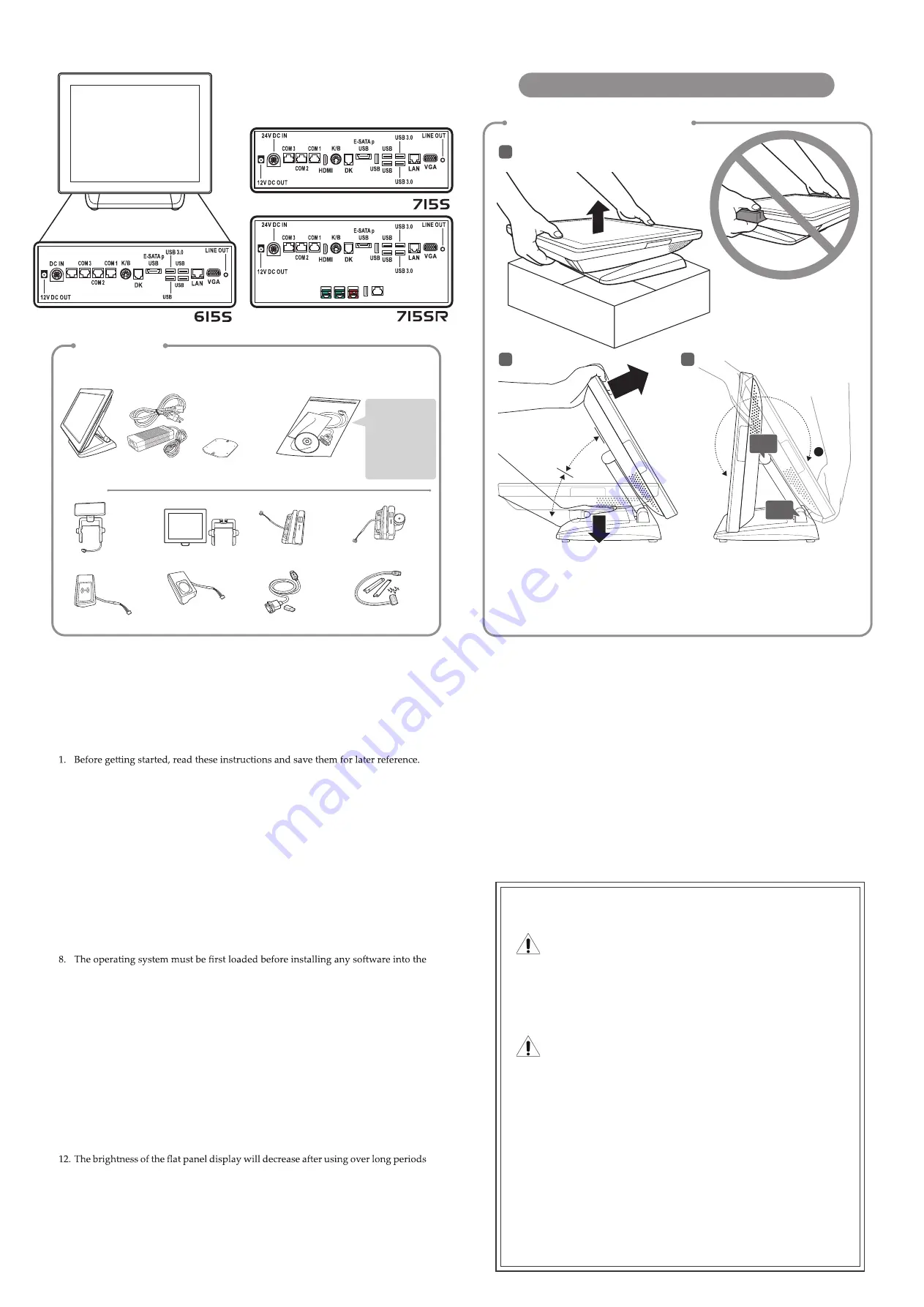
Overview
Technical Support
Safety notices
Before You Proceed
• Read safety notice and User Manual carefully before using the product.
• Keep the box and packaging in case the product needs to be shipped in the future.
• Follow the product and warning label instructions.
• Any changes or modifications that do not follow the instructions in this
manual will void this product's warranty.
Power Supply Safety Notice
• To avoid electric shocks, disconnect the power cord from the electrical
outlet before relocating the system.
• Make sure the voltage of the power outlet conforms within voltage range
of the terminal. Failure to comply may cause the electric shock or damage
to the terminal. If you are not sure of the electricity voltage that you are
using, contact your local electricity company.
• To avoid fire or electric shocks, do not overload electric power outlets.
• Protect the power cord from being walked on or pinched particularly at
plug, convenience receptacles, and the point where they exit from the appa-
ratus.
NOTICE
The version of these drivers and manuals is subject to change without
notice. For update, please contact your local agent.
Warning & Attention
2. Turn off the POS Terminal before cleaning. Clean with dry cloth only. Do not
spray any liquid cleaner directly on the screen.
3. The power outlet socket used to plug in power cord must be located near the
system and easily accessible.
4. Make sure the voltage of the power source is set correctly before connecting the
POS Terminal to power outlet.
5. If the POS Terminal shares an extension cord with other devices, make sure the
total loading of the devices plugged into the extension cord does not exceed the
extension cord’s maximum loading.
6. Do not expose the power cord, extension cord and power outlet to moisture or
traffic intensive walkways.
7. Install the POS Terminal on a sturdy and reliable surface to prevent damage
caused by dropping.
POS Terminal.
9. Disconnect the power cord from the POS terminal before any installation of
internal components. Make sure both the POS terminal and the external devices
are turned off. A sudden surge of power may damage sensitive components.
Also make sure the POS terminal is properly grounded.
10. During installation of any internal components, be sure to ground yourself and
discharge any static electricity. Most electronic components are highly sensitive to
static electric charge. Use a grounding wrist strap and place all electronic compo-
nents in any static-shielded devices. If a wrist-grounding strap is not available,
ground yourself by touching an unpainted piece of metal.
11. The openings on the POS Terminal enclosure are for the cabin ventilation to
prevent the POS terminal from overheating. DO NOT COVER THE VENTILA-
TION OPENINGS.
of time. However, hours of use will vary depending on the application environ-
ment.
13. If the POS Terminal is equipped with a touch panel, avoid using sharp or metallic
objects to operate the touch panel. Scratches on the touch panel may cause
mal-calibration or serious damage to the panel.
14. The LCD panel display is not resistive to shock or vibration. When disassembling
the POS Terminal, make sure the LCD panel is properly and securely installed.
USB 12V
USB 24V
USB 12V
USB COM4
Before setting up the POS Terminal, check the package which contains following
items. If any of the items is missing or damaged, contact your vendor immediately.
Adjust the system stand
RFID
Unpacking
Optional
Main unit
Customer Display
Second LCD Display
MSR
Identification Reader
i-Button
Identification Reader
Wireless Module
Second Hard Disk
Driver Kit
RFID
Identification Reader
Finger Printer
Identification Reader
●
Driver disk
(include
Digital User Manual)
Power cord &
Adapter
●
RJ45 to DB9
Converter cable
VESA plate
(for VESA model only)
Accessory kit
●
Quick Installation
Guide
30°
60°
NOTE 1:
Carefully tilt the unit backwards,
some force is required.
NOTE 2:
Lift the head to the 1st detent where
the screen will lock in the 30-degree position.
Then the 2nd detent will lock in 60-degree
position.
NOTE 1:
Because the stand joints are
tight, you might need to exert some
force to maneuver the Terminal.
NOTE 2:
Make sure always rotate
around the head to the position "a"
before adjusting the upper hinge.
1. To enter the
Boot Menu
, press
F10
.
2.
To set CMOS default, press
F2
to enter
CMOS setting
and load optimized defaults
3. Refer to
User Manual
for other technical information and FAQs. If the problems
are not resolved, contact your local vendor for further support and provide them
with the information below: product name, product serial number, and detailed
description of your problem.
Quick
Installation Guide
COM 4
2.0
2.0
2.0
1
2
3
a
Upper
hinge
Lower
hinge


