D
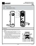
POSITION OF LATCH ON GATE
POSICIÓN DEL CERROJO EN LA PUERTA
POSITION DU LOQUET SUR LE PORTILLON
DETERMINE LEFT- OR RIGHT-HANDED MOUNTING
DETERMINAR LA DIRECCIÓN IZQUIERDA/DERECHA
DÉTERMINEZ LA DIRECTION D’OUVERTURE
1
2
Installation Instructions
LLINSTR0037PA 05/11/18
Procedimientos de instalación
3
1
/
2
”
(90 mm)
5
/
32
” (4 mm)
1
/
2
” (13 mm)
#
2
#
2
Instructions d’installation
5
/
8
” (16 mm)
For vinyl & wood
Para vinilo y madera
Pour vinyle et bois
3
⁄
8
”–1
1
⁄
16
” (10-27 mm)
GAP VARIANCE:
DIFERENCIA DE ESPACIO:
ÉCART D’ESPACEMENT :
GATE FRAME
Marco de la puerta
Cadre de portillon
FENCE POST
Poste de cerca
Poteau de clôture
LEFT
IZQUIERDA
GAUCHE
RIGHT
DERECHA
DROITE
Rotate (flip) Mounting Bracket (A) to obtain the
required Left or Right handing
Rote (gire) el soporte de montaje (A) para determinar si abrirá
hacia la izquierda o hacia la derecha, según lo que necesite.
Faites pivoter (retournez) le support de fixation (A) pour
obtenir une ouverture vers la gauche ou vers la droite.
A
Step 1:
Determine the height of latch on the fence
post. Use the Mounting Bracket (A) as a fitting jig
to mark the side of post, aligning with the lower
notch on the Bracket as shown.
Paso 1: determine la altura del cerrojo en el poste de la
cerca. Utilice el soporte de montaje (A) como una plantilla
de posición para marcar el lado del poste, alineándolo con la
ranura más baja del montaje como se muestra en la imagen.
1
ère
étape : déterminez la hauteur du loquet sur le poteau
de la clôture. Utilisez le support de fixation (A) comme
gabarit pour marquer le côté du poteau, en l’alignant sur
l’encoche inférieure du support, comme indiqué.
Step 2:
Slide the Mounting Bracket down so that
the center notch now aligns with your marked line.
Mark that point on the post face, which will be
3
⁄
4
”
(19mm) in from the outer edge.
Paso 2: deslice el soporte de montaje hacia abajo para
que la ranura central coincida con la línea que marcó.
Marque ese punto en la cara del poste, que se ubicará a
3⁄4” (19 mm) hacia adentro desde el borde exterior.
2
ème
étape : faites glisser le support de fixation vers le
bas de sorte que l’encoche centrale s’aligne maintenant
avec la ligne que vous avez faite. Marquez ce point sur le
poteau, à 19 mm du bord extérieur.
Step 3:
Take the Mounting Bracket around to
the opposite side of post and mark the opposing
point, being sure to again align with the center
notch on the Bracket.
Paso 3: tome el soporte de montaje alrededor del lado
contrario del poste y marque el punto contrario, asegurándose
nuevamente de alinear la ranura central en el soporte.
3
ème
étape : placez le support de fixation sur le côté opposé
du poteau puis marquez le point opposé en vous assurant
de l’aligner à nouveau sur l’encoche centrale du support.
3
⁄
4
”
(19 mm)
CONNECTING ROD: CUTTING TO SIZE & SEATING
VARILLA DE CONEXIÓN: CORTAR A
MEDIDA Y COLOCAR
TIGE DE CONNEXION : COUPE AUX
DIMENSIONS ET FIXATION
3
Step 1:
Insert Connecting Rod (B)
through fence post.
Paso 1: inserte la varilla de conexión (B)
a través del poste de la cerca.
1
ère
étape : insérez la tige de connexion
(B) à travers le poteau de la clôture.
B
Step 2:
Slide the Rod so that the pointy
end aligns flush with the outside of the
post, as shown below. Mark the Rod on
the opposite side of post and remove.
Paso 2: deslice la varilla hasta que el extremo
con punta se alinee al ras con el lado exterior
del poste, como se muestra debajo. Marque la
varilla en el lado contrario del poste y retírela.
2
ème
étape : faites glisser la tige de sorte que
l’extrémité pointue s’aligne sur l’extérieur du
poteau, comme illustré ci-dessous. Marquez
la tige sur le côté opposé du poteau puis
retirez-la.
Step 3:
The Rod should now be
marked to the same depth as your
post.
Use the hacksaw to cut the Rod to
length. Remove any burrs.
Paso 3: la varilla debería estar marcada ahora
a la misma profundidad que su poste. Utilice la
sierra para metales para cortar la varilla del largo
necesario. Elimine todos los bordes mal acabados.
3
ème
étape : la tige devrait maintenant être marquée
à la même profondeur que votre poteau. Utilisez
une scie à métaux pour couper la tige à la longueur
voulue. Enlevez toutes les bavures.
Note the lower notch on side of
Mounting Bracket
Vea la ranura más baja del
soporte de montaje.
Notez la fente inférieure sur le
côté du support de fixation
A
Side face
of post
Front face
of post
Side (depth)
of post
Lado (profuxndidad)
del poste
Côté (profondeur)
du poteau
Step 4:
Insert the Rod into the
External Access Push-Button (C)
housing until it snaps into place.
Paso 4: inserte la varilla en el botón de
acceso externo (C) hasta que encaje en la
posición adecuada.
4
ème
étape : insérez la tige dans le
logement du bouton-poussoir d’accès
externe (C) jusqu’à ce qu’elle s’enclenche.
C
Step 5:
Insert the connected unit so that
the rod slides fully through the post. Fix it in
place using four screws.
Paso 5: inserte la unidad conectada para que la
varilla se deslice por completo a través del poste.
Fíjela en el lugar con los cuatro tornillos.
5
ème
étape : insérez l’unité connectée de sorte que
la tige glisse complètement à travers le poteau.
Fixez-la en place à l’aide de quatre vis.
Step 7:
Depress the
push-button so that the
sawn Rod protrudes out
from the post.
Paso 7: pulse el botón
para que la varilla
cortada sobresalga
del poste.
7
ème
étape : appuyez
sur le bouton-poussoir
pour que la tige sciée
dépasse du poteau.
Step 8:
Position the
Latch Body (D) so that the
protruding rod slots into the
corresponding interface (E) -
see below - and then mount
the Body with four screws.
Paso 8: ubique la estructura del
cerrojo (D) para que la varilla
sobresaliente se inserte en la
interconexión correspondiente
(E) (ver la imagen debajo) y
luego instale la estructura con
cuatro tornillos.
8
ème
étape : positionnez le corps
du verrou (D) de sorte que la
tige en saillie se place dans
l’interface correspondante (E)
- voir ci-dessous - puis fixez le
corps à l’aide de quatre vis.
E
For child safety gates use the MagnaLatch
®
‘Top Pull’ Gate Latch.
Usar MagnaLatch
®
Cerrojo para puertas de seguridad para niños
Utilisez le verrou de portillon MagnaLatch
®
pour les barrières de sécurité enfants
5
⁄
32
” (4 mm)
1
⁄
2
” (13 mm)
Step 4:
Drill holes through post, starting with pilot
holes of
5
⁄
32
” (4mm) on both sides of the post.
With pilot holes complete, enlarge the holes by
redrilling with the larger
1
⁄
2
” (13mm) drill bit.
Paso 4: perfore el poste con el taladro; comience con orificios
de prueba de 5⁄32” (4 mm) en ambos lados del poste. Una
vez que haya hecho los orificios de prueba, agrándelos con el
taladro con una broca más grande de 1⁄2” (13 mm).
4ème étape : percez des trous dans le poteau, en
commençant par les avant-trous de 4 mm des deux côtés
du poteau. Une fois les trous percés, agrandissez les trous
en utilisant un foret plus grand de 13 mm.
Step 9:
Take the Striker Body
(F) and, centering the bolt in
the middle of the tongue slot,
fix it with four more screws,
being sure to mount the
screws in the center of the
slots.
Paso 9: tome la estructura del
cerradero (F) y, centrando el perno
en el medio del orificio de la
lengüeta, fíjelo con otros cuatro
tornillos asegurándose de colocarlos
en el centro de los orificios.
9
ème
étape : prenez la barre de
butée (F) puis, en centrant le
verrou au milieu de la fente de
la languette, fixez-la avec quatre
autre vis, en veillant à monter les
vis au centre des fentes.
D
F
Center screws in slots
Centre los tornillos en los orificios.
Centrez les vis
dans les fentes
LEFT-HANDED
MOUNTING SHOWN
Step 6:
Use the four small
screws to secure Mounting
Bracket to the Latch Body.
Paso 6: utilice los cuatro tornillos
pequeños para asegurar el soporte
de montaje a la estructura del cerrojo.
6
ème
étape : utilisez les quatre petites
vis pour sécuriser le support de
fixation au corps du verrou.
SE MUESTRA LA
INSTALACIÓN PARA
ABRIR HACIA LA
IZQUIERDA
MONTAGE À GAUCHE
ILLUSTRÉ