Danaher Motion CP303, Installation Manual
The Danaher Motion CP303 is a precise and efficient control system ideal for a variety of applications. Ensure optimal operation by accessing the free Installation Manual. Enhance your understanding and maintenance capabilities by downloading the manual directly from manualshive.com. Get your free download today and maximize your device's performance.
Share
Download


Reviews:
No comments
Related manuals for CP303

ELTRAL VA35
Brand: GU Pages: 13

DFPI-***-***-ND2P-E-P-G2
Brand: Festo Pages: 4

FC103-110-250Kw
Brand: Danfoss Pages: 77

SST-TOB02
Brand: SilverStone Pages: 2

CNMD180W0ENNNC1
Brand: Rockwell Automation Pages: 248

Allen-BradleyPowerFlex 700AFE
Brand: Rockwell Automation Pages: 296

5630
Brand: Pacific Scientific Pages: 58

QMS-430
Brand: Binks Pages: 8

IM.60 24V + CPS
Brand: Fancom Pages: 55

CSDJ Plus
Brand: OE Max Controls Pages: 58

ADB-2640U
Brand: Melec Pages: 42

SGD7S-R70A20A023F40B
Brand: YASKAWA Pages: 342

2K2100
Brand: ZF-DUOPLAN Pages: 34

ISMATEC BVP-Z
Brand: Idex Pages: 28

AC60 series
Brand: Veichi Electric Pages: 191

XLT50-D
Brand: Parker Pages: 12

G-SOLWHI10/100E
Brand: Elmo Pages: 64
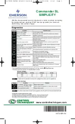
Control Techniques Commander SL Series
Brand: Emerson Pages: 2


