Live Score Bug Quick Guide
DD4842953
Rev 00
07 May 2021
201 Daktronics Drive
Brookings, SD 57006-5128
www.daktronics.com/support
800.325.8766
Page 1 of 5
This guide explains the setup
of Daktronics Live Score Bug
to output a Network Device
Interface (NDI) or HDMI feed
to a compatible customer-
provided streaming device.
The kit includes the following
devices and cables:
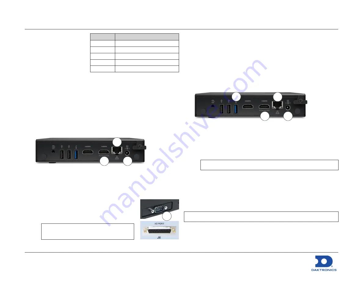
Live Score Bug Device Connection
With Fixed-Digit Scoreboards
This setup will receive Real-Time Data (RTD) from an All Sport
®
5000
console that controls a fixed-digit numeric scoreboard.
1.
Unpack all items and verify all parts listed above are included.
2.
Locate the Live Score Bug device, and set it within 14' of the
streaming device and within 16' of the All Sport 5000 console.
3.
Make the following connections:
a.
Connect the power adapter between the Live Score Bug
device and a standard wall outlet. Verify power LED turns on.
b.
Connect a 14' Ethernet cable between the network jack on
the Live Score Bug device and the Local Area Network (LAN)
switch/router used by the streaming device.
c.
Connect the 6' serial cable between the
9-pin serial port on the Live Score Bug
device and the 25-pin
J6 I/O PORT
on the
All Sport console. Use 10' cable if needed.
Note:
Existing All Sport connection may
vary by site.
d.
If outputting to HDMI, use the
HDMI Protected UHD
jack.*
3b
3a
3d
3c
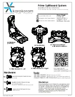
With Video Displays
This setup will receive Real-Time Data (RTD) over an existing
Daktronics video display control network. The RTD may be coming
from an All Sport 5000 console or All Sport Pro software.
1.
Unpack all items and verify all parts listed above are included.
2.
Locate the Live Score Bug device, and set it within 14' of the
streaming device.
3.
Make the following connections:
a.
Connect the power adapter between the Live Score Bug
device and a standard wall outlet. Verify power LED turns on.
b.
Connect one 14' Ethernet cable between the network jack
on the Live Score Bug device and the Local Area Network
(LAN) switch/router used by the streaming device.
Note:
If this is also the Daktronics network, skip to step (d).
c.
Use the USB-to-Ethernet adapter and the second 14' Ethernet
cable to connect the Daktronics network switch/router to the
Live Score Bug device.
d.
If outputting to HDMI, use the
HDMI Protected UHD
jack.*
Note:
Refer to
DWG-4841630
for detailed connection diagrams.
*The Live Score Bug device must be located within reach of the HDMI
cable to the video capture device.
3b
3c
3a
3d
Part #
Description
0A-2122-0100 Live Score Bug Device
A-2715
USB-to-Ethernet Adapter
W-1249
6' Serial Cable (9-pin to 25-pin)
W-1267
10' Serial Cable (9-pin to 9-in)
W-1343
14' Ethernet Cable (qty. 2)