

Quick Reference
930937C
© 2017, CyberData Corporation, ALL RIGHTS RESERVED
© 2017, CyberData Corporation, ALL RIGHTS RESERVED
930937C
Quick Reference
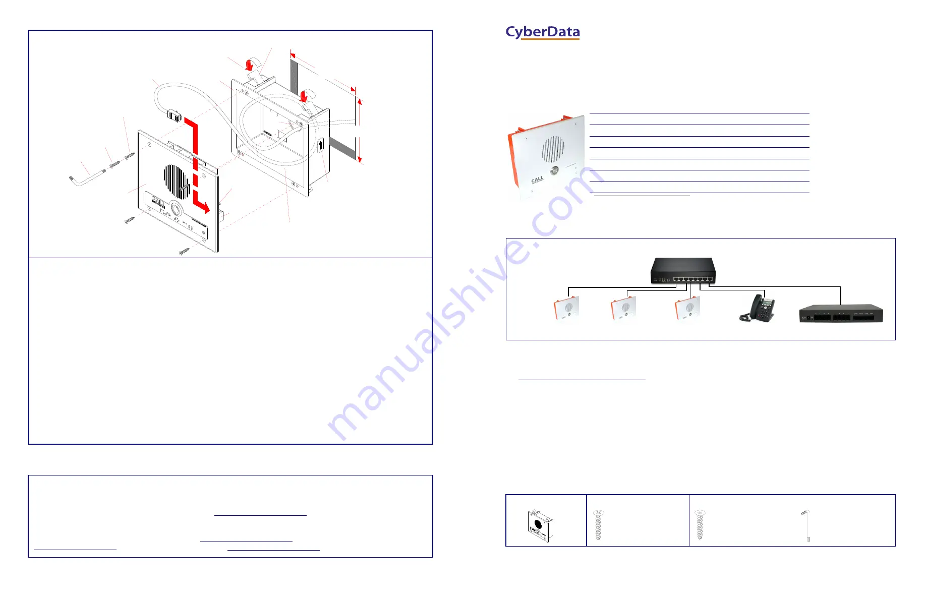
Mounting Options
Contacting CyberData
Fold Down all Flagnuts (4 Places)
before Inserting into Wall Cutout
Cutout
Network Cable
(Not Provided)
Screws
Faceplate
2 Gang Box
Torx Drive)
Assembly
Ground Wire &
Point Upward.
Arrow Labels must
This will Ensure that
the Intrusion Sensor
Functions Properly.
Wall
Inside Gang Box
Create Service Loop
Torx Key
(Phillip Drive)
(Security
Mounting
Screws
Mounting
Flagnuts
(4 Places)
K.O.
to J1
6.03 inches
[153mm]
5.28 inches
[134mm]
Network Cable
J1
Intrusion
Sensor
1
8
7
3
9
9
4
6
2
5
To mount the Intercom:
1. Make a wall cutout as shown in the picture.
2. Use a flat blade screwdriver to remove the knockout (KO) of the gang box.
3. Feed the ground wire (shown in the “
Ground Connection
” section) and the network cable from the wall cutout through the
knockout hole of the gang box.
4. Create a service loop for both the ground wire and network cable.
5. Plug the network cable into the J1 connector.
6. Make sure that the arrow labels on the sides of the gang box are pointing up. This will ensure that the intrusion sensor
functions properly.
7. Fold down all of the flagnuts, and then insert the gang box into the wall cutout.
8. Tighten the flagnuts with a size #2 Phillips screwdriver.
9. Use a size #2 Phillips screwdriver to secure the Intercom faceplate assembly to the gang box with either Phillips drive
screws or security Torx drive screws.
Custom
Enclosure
Create Service Loop
Inside Custom Enclosure
Sales: (831) 373-2601 ext. 334
Support: 831-373-2601 ext. 333
Support Website:
RMA Department: (831) 373-2601 ext. 136
RMA Email: [email protected]
RMA Status:
Warranty Information:
http://support.cyberdata.net/
Corporate Headquarters
CyberData Corporation
3 Justin Court
Monterey, CA 93940, USA
Phone: 831-373-2601
Fax: 831-373-4193
Typical System Installation
Getting Started
•
Download the
Operations Guide
PDF file, from the
Downloads
tab at the following webpage:
http://www.cyberdata.net/voip/011306
•
Create a plan for the locations of your Intercoms.
•
WARNING: This product should be installed by a licensed electrician according to all local electrical and building codes.
•
WARNING: To prevent injury, this apparatus must be securely attached to the floor/wall in accordance with the installation
instructions.
•
WARNING: The PoE connector is intended for intra-building connections only and does not route to the outside plant.
•
WARNING: This enclosure is not rated for any AC voltages!
Intercom Parts
Tool required for assembly: A size #2 Phillips screwdriver
Parameter
Factory Default Setting
IP Addressing
DHCP
IP Address
a
10.10.10.10
Web Access Username
admin
Web Access Password
admin
Subnet Mask
a
255.0.0.0
Default Gateway
a
10.0.0.1
a. Default if there is not a DHCP server present.
802.3af Compliant Ethernet Switch
Intercom
IP Phone
Informacast Server
Intercom
Intercom
*
More installation and mounting
options are available in the
Operations Guide
.
(4) #6 X 3/8-inch,100 Deg.,
Flat Head, Self-Tapping Screw
(1) Intercom Assembly
(1) Mounting Kit
(4) #6 X 3/8-inch,100 Deg.,
Flat Head T15 Security Pin Torx
Screw
(1) T15 Security Pin Torx Key
(1) Optional Mounting Kit
The IP Endpoint Co
m
pan
y
Installation Quick Reference
Singlewire InformaCast Indoor Intercom Flush Mount
SIP Compliant
011306


