

Rugged, Reliable, Mobile, Secure
TM
1-800-260-9800
www.CRU-DataPort.com
Package Contents
1 - DataPort frame assembly
1 - DataPort carrier assembly
2 - Metal covers
4 - 6 x 32 x 3/8” flat-head screws for hard drive mounting
4 - M3 x 10mm Phillips pan-head screws for frame mounting
2 - Keys for lock
1 - Cover removal tool
Frame Installation
1. Turn off the computer and disconnect the power cord from the
electrical outlet. Before working on the computer, wait one
minute for any residual energy to dissipate. Ground yourself
by touching the chassis of the computer.
2. Locate an available 5.25” drive bay with external access. Re-
move the cover of the computer. Identify the 5.25” half-height
bay in which the DataPort frame assembly will be mounted.
Examine the bay to determine the location of mounting holes
or whether mounting rails are required. Remove any filler
plates that may be present on the computer.
3. Rail mounting the frame. If the drive bay requires mounting
rails, install one on each side of the frame. The mounting rails
should be provided with the computer system.
4. Direct mounting the frame. Slide the frame into the 5.25” bay,
some computer bezels will not allow the frame to be inserted
from the front. Install the frame from inside the computer.
Secure the frame with the screws provided.
5. Connect the DC power cable to the frame. Locate an available
4-pin DC power cable from the computer power supply and
plug it into the receptacle on the frame.
6. Connect the data cable to the frame. Locate an available SCSI
connector on the SCSI cable and connect it to the data connec-
tor on the frame.
The frame installation is now complete; follow the instruc-
tions below for carrier installation.
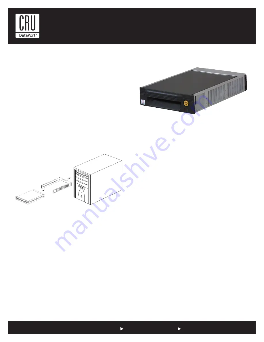
Mounting a Hard Drive In The Carrier
1. Remove the carrier’s top and bottom covers. The metal covers
for the DataPort carrier are snapped into place on the carrier
without any screws. Use the supplied cover removal tool or a
small flat head screwdriver for this task.
2. Connect the SCSI ID selector switch to the SCSI ID selector
header on the hard drive. See Connecting the SCSI ID Selector
Switch section in the Operation section for more details.
3. Plug the 4-pin DC power cable into the power connector on the
hard drive and ensure it is fully seated.
4. Connect the data cable in the carrier to the hard drive for 50-
pin and 68-pin SCSI drives. For SCA drives connect the hard
drive to the connector on the circuit board.
5. Place the drive in the carrier and use the four screws provided
to side-mount the hard drive. Position the cables inside the
carrier assembly so that they are completely enclosed within
the carrier. For DataPort 5+ and 6, attach the Temperature
Control Cooling Sensor (TCCS) to the top of the hard drive with
an adhesive strip (or a piece of tape). Replace the top and bot-
tom covers on the carrier.
6. Position the carrier on the frame’s guide rails and slide the
carrier in. Using thumb pressure, fully seat the carrier in the
frame and lock the carrier with the keylock. The installation is
complete and the DataPort is ready for operation.
DataPort 5 & 5+ and 6 SCSI Install Guide


