

USB-EXT-2
USB over Twisted Pair Extender
Installation Guide
Description
The Crestron
®
USB-EXT-2 enables high-speed USB signals to be extended up to
330 feet (100 meters) over one CAT5e (or better) twisted-pair cable, and power can be
supplied to the USB-EXT-2 through either the local extender or the remote extender.
The USB-EXT-2 is compatible with almost any USB 1.1 or USB 2.0 device, and it is
compatible with host computers running Windows
®
software, macOS
®
software, and
Linux
®
software without needing to install any additional drivers.
Additional Resources
Visit the product page on the Crestron website (www.crestron.com)
for additional information and the latest firmware updates. Use a QR
reader application on your mobile device to scan the QR image.
Mounting the Extenders
After determining the location of the local host computer and the remote USB device(s),
place the USB-EXT-2 local extender on a secure, level surface near the host computer,
and place the USB-EXT-2 remote extender on a secure, level surface near the USB
device(s). The rubber feet on the bottom of each extender help to prevent the extenders
from shifting.
Connecting the Extenders
Use the following procedure to connect the USB-EXT-2 extenders:
1. Connect the USB B end of the included USB cable into the local extender, and then
connect the USB A end of the cable into a USB type A port on the host computer.
2. Connect one RJ45 connector end of a CAT5e (or better) unshielded twisted-pair
(UTP) cable to the Link port on the local extender, and then connect the other RJ45
connector end to the Link port on the remote extender.
CAUTION
: Do not connect the Link ports of the local extender or the remote
extender to an Ethernet LAN or any other network device.
NOTE
: Ensure that the chosen CAT5e (or better) UTP cable does not exceed
330 feet (100 meters). The cable must have a straight-through conductor
configuration with no crossovers and must be terminated with 8-conductor RJ45
connectors at both ends.
NOTE
: If using preinstalled in-wall CAT wiring, connect one RJ45 connector end
of a CAT5e (or better) patch cable to the Link port of the local extender, and
connect the other RJ45 connector end to the CAT wall outlet near the host
computer. Then, connect one RJ45 connector end of a CAT5e (or better) patch
cable to the Link port of the remote extender, and connect the other RJ45
connector end to the CAT wall outlet near the USB device(s). Ensure that the two
patch cables and the in-wall cabling do not exceed 330 feet (100 meters) in total.
3. Connect the included ac power supply to either the local extender or the remote
extender, and then plug the other end of the power supply into an ac power source.
CAUTION
: Supply ac power to only one of the two extenders. Never supply ac
power to both extenders at the same time.
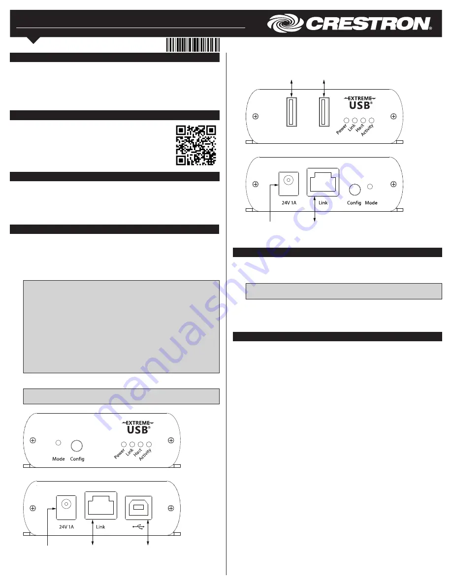
USB-EXT-2 Local Extender Connections (Front and Rear)
Connecting the USB Devices
Use the following procedure to connect the remote USB device(s) to the USB-EXT-2:
1. Install any software on the host computer that is required to operate the USB
device(s). Refer to the USB device documentation for installation instructions.
NOTE
: Crestron does not guarantee that the USB-EXT-2 is compatible with all
USB devices.
2. Connect the USB device(s) to either USB port on the remote extender using a
standard USB cable.
3. Confirm that each USB device is properly installed on the host computer and that it
is detected by the operating system.
Checking the Installation
Check that the Power, Activity, Link, and Host LEDs light on both the local extender and
the remote extender. If the Link or Host LEDs do not light, then the cabling between the
local extender and the remote extender may be installed incorrectly or may be defective.
Additionally, check to see whether USB-EXT-2 extender system has been installed
correctly on the host computer. Refer to the below instructions.
For Windows Software:
1. Open
Device Manager
.
2. Expand the
Universal Serial Bus controllers
node.
3. Check to see if the extender system appears on the list of controllers. If the extender
system has been properly installed, it appears on the list as a “Generic USB Hub.”
For macOS Software:
1. Open
System Profiler
.
2. In the left column under
Hardware
, select
USB
.
3. Check to see if the extender system appears in the
USB Device Tree
at the top right
of the System Profiler window. If the extender system has been properly installed, it
is listed as a “Hub” under the
USB High-Speed Bus/USB Bus
node.
If the USB-EXT-2 extender system does not detect correctly or fails to detect, refer to the
“Troubleshooting” section on the next page.
Link:
To USB-EXT-2
remote extender
USB B:
To host computer
or USB hub
24V 1A:
From included
power pack
USB-EXT-2 Remote Extender Connections
Link:
To USB-EXT-2
local extender
24V 1A:
From included
power pack
USB A:
To remote
USB device
USB A:
To remote
USB device


