Concept Pro VHSDIR-812EXT-IP3M, User Manual
Looking for the user manual for the Concept Pro VHSDIR-812EXT-IP3M? Look no further! Our website offers a free download of the manual, providing you with all the information you need to maximize the potential of this incredible product. Get your hands on it now at manualshive.com!
Share
Download


Reviews:
No comments
Related manuals for VHSDIR-812EXT-IP3M

8204
Brand: UniPOS Pages: 2

DCS-820L
Brand: D-Link Pages: 16

48NDVA
Brand: M-system Pages: 9

FI8601W
Brand: Foscam Pages: 16

VistaCam 1103
Brand: eZLO Pages: 10

X2-VIDEO-200
Brand: X2 Digital Wireless Systems Pages: 16

WPIR-CRT
Brand: Vanderbilt Pages: 3

VK2-1080MD37PTW
Brand: Vista Pages: 15

MAGPRO16
Brand: ESP Pages: 55

CVC6940
Brand: Lorex Pages: 1

CamView PTZ 2
Brand: Triplett Pages: 44

SECVEST
Brand: Abus Pages: 61

MINI CND
Brand: Sminn Pages: 2

IV-8MP180DE
Brand: Idview Digital Pages: 2

DS-PDD12P-EG2-WB
Brand: HIKVISION Pages: 6

BWX560
Brand: General Lock Pages: 6
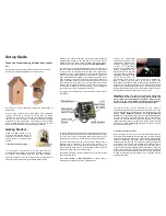
Nest Box Camera System
Brand: Gardenature Pages: 2

10211
Brand: NA-DE Pages: 2


