Clarke 3402041, Operation & Maintenance Instructions Manual
The Clarke 3402041 is a versatile product designed for various applications. Ensure optimal performance with the Operation & Maintenance Instructions Manual available for free download from our website. This comprehensive manual provides detailed guidance on proper usage and maintenance of the product. Get your manual today!
Share
Download


Reviews:
No comments
Related manuals for 3402041
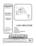
LS67528S
Brand: Swisher Pages: 12

95452
Brand: PAPILLON Pages: 18

VH0622
Brand: Brave Pages: 48

THLS-6
Brand: The Handy Pages: 8

THMLS
Brand: The Handy Pages: 12

THLS-C
Brand: The Handy Pages: 13

THLS-6-PLUS
Brand: The Handy Pages: 24

S402022H0
Brand: Oregon Scientific Pages: 20

LS 405D
Brand: Far Tools Pages: 25

HL460
Brand: Scheppach Pages: 112

HL710
Brand: Scheppach Pages: 120

5905421902
Brand: Scheppach Pages: 336

ASP 5-UG
Brand: ATIKA Pages: 122

ASP 4 - 370 - 2
Brand: ATIKA Pages: 122

ASP 4 N
Brand: ATIKA Pages: 136

ASP 10 N-400
Brand: ATIKA Pages: 147

ASP 5 N-UG
Brand: ATIKA Pages: 148

ASP 12 TS
Brand: ATIKA Pages: 148


