background image

INSTRUCTION MANUAL

(M98251301-03-16A)

Earth leakage relay

RGU-2

Summary of Contents for RGU-2

Page 1: ...INSTRUCTION MANUAL M98251301 03 16A Earth leakage relay RGU 2...

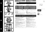
Page 2: ...2 RGU 2 Earth Leakage Relay Instruction Manual...

Page 3: ...ad the manual carefully prior to connecting the unit Follow all installation and maintenance instructions throughout the unit s working life Pay special attention to the installation stan dards of the...

Page 4: ...RY RELAY AUX 16 5 6 PROGRAMMING 17 5 6 1 TRIP CURRENT I n and TRIP DELAY TIME td 17 5 6 2 PROGRAMMING THE AUXILIARY RELAY AUX 18 5 6 3 FREQUENCY AND STATUS OF THE OUTPUT RELAY CONTACTS 18 5 6 4 LOCKIN...

Page 5: ...log Date Revision Description 10 13 M98251301 03 13A Initial Version 11 13 M98251301 03 13B Modified Figure 1 05 16 M98251301 01 16A Modification section 2 3 3 3 4 5 6 1 5 7 1 5 7 2 6 5 Instruction Ma...

Page 6: ...detecting element or sensor A relay A circuit breaker The unit is fully programmable It is supplied with the following 3 Keys used to TEST RESET and program the unit 2 operation LEDs that display the...

Page 7: ...dents personal injury and damage to installations The manufacturer of the unit is not responsible for any damages resulting from failure by the user or installer to heed the warnings and or recommenda...

Page 8: ...disconnect the unit from the power supply mains Note The connection diagram suggests a cable section of 1 1 5 mm Recommended torque 0 5 0 6 Nm Terminals opening covers or removing elements can expose...

Page 9: ...system with RESET Figure 2 Connection diagram of the unit as a protection element shunt coil trip B UNDERVOLTAGE COIL TRIP Manual reclosing system with RESET Figure 3 Connection diagram of the unit a...

Page 10: ...3 4 2 AS A MONITOR RCM Figure 4 Connection diagram of the unit as a monitor 10 RGU 2 Earth Leakage Relay Instruction Manual...

Page 11: ...is supplied with the following default factory configuration Trip current scale I n 30mA Trip time scale td Instantaneous curve IN Frequency 50 Hz Auxiliary relay function Fault relay Polarity of the...

Page 12: ...hen the instantaneous leakage current has been measured the RGU 2 unit will operate in accordance with the programmed parameters Trip current I n Trip delay time td As a result the status of the devic...

Page 13: ...it LCD The background will be green under normal conditions The display will be red in case of events that cause an action protection trigger or circuit breaker being tripped Figure 8 Display The foll...

Page 14: ...gure 11 Figure 11 Trip current screen Example 45mA trip current Floating screens can also be displayed they will be shown during 5 seconds and then return to the fixed active screen such as AUX relay...

Page 15: ...ccordance with the selected trip scale Table 3 LED Bar Leakage current level Color LED bar 20 40 60 Green 80 Yellow 100 Red 5 4 INPUTS The unit has two inputs External current sensor input terminals 1...

Page 16: ...rlocking Its operation can be programmed as a prealarm or fault relay refer to 5 6 2 PROGRAMMING THE AUXILIARY RE LAY AUX Prealarm ALAR activated when the I 0 5 I n in 200 milliseconds The logical sta...

Page 17: ...ROG key PROG If changes have been applied SAVE will be displayed for 3 seconds and the unit will exit the programming screens If changes have not been applied EXIT will be displayed for 3 sec onds and...

Page 18: ...the auxiliary relay RESET Prealarm ALAR This is activated when I 0 5 I n in 200 milliseconds Fault relay AUXF Shows fault events in the unit such as undervoltages or faults in the external sensor Ope...

Page 19: ...the PROG key Status of the AUX relay contact STD by default STD Standard NO status POS NC positive safety status When this option is activated the sign will appear on all screens that refer to the AUX...

Page 20: ...OY Y appears flashing Locked keyboard Accept with the PROG key If changes have been applied SAVE will be displayed for 3 seconds and the unit will exit the programming screens If changes have not been...

Page 21: ...5 only changes its status if it has been configured as a pre alarm DISPLAY Fixed red screen that shows the leakage with the earth leakage symbol Figure 16 Figure 16 Leakage screen Prealarm symbol whe...

Page 22: ...changes its status if it has been configured in the fault mode with positive safety When the power supply voltage is below the minimum operating voltage of the unit the relay output will change its st...

Page 23: ...breaker MCB MCCB with coil is set to OFF 2 The unit returns to the normal operating conditions after the RESET key has been pressed 3 Finally the ON circuit breaker is activated manually Note In case...

Page 24: ...auxiliar relay AUX Maximum voltage open contacts 1000V Isolation voltage 2000V Thermal current Ith 5A Maximum switching power 1250 VA 150W Electrical life 3A 105 Environmental characteristics Work tem...

Page 25: ...Figure 21 Dimensions of the RGU 2 25 Instruction Manual RGU 2 Earth Leakage Relay...

Page 26: ...rating or storage condition con trary to the national electrical code or that surpasses the limits indicated in the technical and environmental features of this manual CIRCUTOR accepts no liability du...

Page 27: ...9 CE CERTIFICATE 27 Instruction Manual RGU 2 Earth Leakage Relay...

Page 28: ...APPENDIX A TRIP CURVES Figure 22 Instantaneous Trip Curve Figure 23 Selective Trip Curve INSTANTANEOUS CURVE INS SELECTIVE CURVE SEL 28 RGU 2 Earth Leakage Relay Instruction Manual...

Page 29: ...29 Instruction Manual RGU 2 Earth Leakage Relay...

Page 30: ...CIRCUTOR SA Vial Sant Jordi s n 08232 Viladecavalls Barcelona Tel 34 93 745 29 00 Fax 34 93 745 29 14 www circutor es central circutor es...

Reviews: