

Le schede elettroniche PCOS00KX** sono dispositivi opzionali che permettono ai controlli della
linea pCO ed e-drofan di essere collegati ad una rete operante secondo lo standard Konnex.
PCOS**KXB0
Modello per la porta pCO BMS, alloggiamento “Serial card” ed e-drofan
PCOS00KXF0
Modello per la porta Field-bus del pCO
3
, alloggiamento “Field card”
Montaggio su pCO
Con riferimento alle Fig. 2-5, l’installazione nel pCO* si ottiene a macchina non alimentata secondo la
seguente procedura:
1. Con un cacciavite, togliere lo sportellino “serial card” o fi eld card, a seconda del modello, del pCO (vedi
Fig. 2);
2. Con un tronchesino, eliminare dallo sportellino la parte plastica prefratturata, ottenendo il foro corrispon-
dente all’uscita del connettore a 2 vie (vedi Fig. 3);
3. Inserire la scheda opzionale nel corrispondente connettore, assicurandosi che la scheda sia ben inserita
e a contatto dei due appoggi posti sul contenitore del pCO (vedi Fig. 4).
Attenzione! L’inserimento della scheda e l’accoppiamento dei connettori potrebbero risultare diffi coltosi a
causa dello spazio esiguo e dei due appoggi plastici. Si consiglia l’inserimento obliquo della scheda e la sua
rotazione fi no a far combaciare i connettori.
4. Richiudere lo sportellino facendo combaciare il connettore della scheda seriale con il foro eseguito sullo
sportellino (vedi Fig. 5).
Montaggio su e-drofan
Con riferimento alla fi g 6, l’installazione nell’e-drofan si ottiene a macchina non alimentata, inserendo la
scheda opzionale nel corrispondente connettore, assicurandosi che la scheda sia ben inserita (fi g 6b).
Agganciare ed avvitare il supporto plastico (incluso nella confezione) come da fi gura 6c e 6d.
Confi gurazione parametri comunicazione pCO ed e-drofan
pCO
e-drofan
Baudrate
9600 Baud
fi sso 9600 Baud
Indirizzo
1
P69=1
Protocollo
Modbus
P54=1
Confi gurazione e connessione alla rete Konnex
Per la confi gurazione della scheda e necessario il software ETS3, ETS4, il fi le CAREL-plugin-xx.pr4 ed il tool
KSet (disponibile su ksa.carel.com).
TOOL
Funzione
KSet
Associazione registri Modbus
®
a datapoint Konnex
Assegnazione indirizzi di gruppo per ogni datapoint
ETS3, ETS4
Assegnazione indirizzo di rete del dispositivo
Scaricamento fi le .xlm
Seguire la seguente procedura:
1) creare un nuovo progetto o aprire un progetto preesistente
2) importare il project database CAREL-plugin-xx.pr4
3) defi nire gli indirizzi di gruppo per tutti i datapoint
4) Da KSet: aprire o creare un nuovo fi le xxx.XML, defi nire la lista di associazioni tra datapoints KNX e registri
Modbus
®
riportare nella colonna “gruppi” gli indirizzi di gruppo impostati tramite ETS3, ETS4 dei datapoints
da condividere e, al termine, salvare la confi gurazione (fi le .xml)
5) Da ETS3, ETS4: a) Aprire ETS3, ETS4 e aggiungere i dispositivi CAREL
b) Assegnare ad ogni dispositivo l’indirizzo utilizzando la procedura standard (pressione
del pulsantino presente sulla scheda (vedi fi gura 1).
Confi gurare la scheda scaricando il fi le .XML salvato in precedenza (Tramite il menù Proprietà del plug-in,
selezionare poi CAREL device confi guration ( usare per far apparire il menù).
+050000770 - rel. 1.2 - 14/02/2013
PCOS**KXB0, PCOS00KXF0
Scheda KONNEX per pCO
XS
/pCO
1
/pCO
3
/e-drofan - KONNEX board for pCO
XS
/pCO
1
/pCO
3
/e-drofan
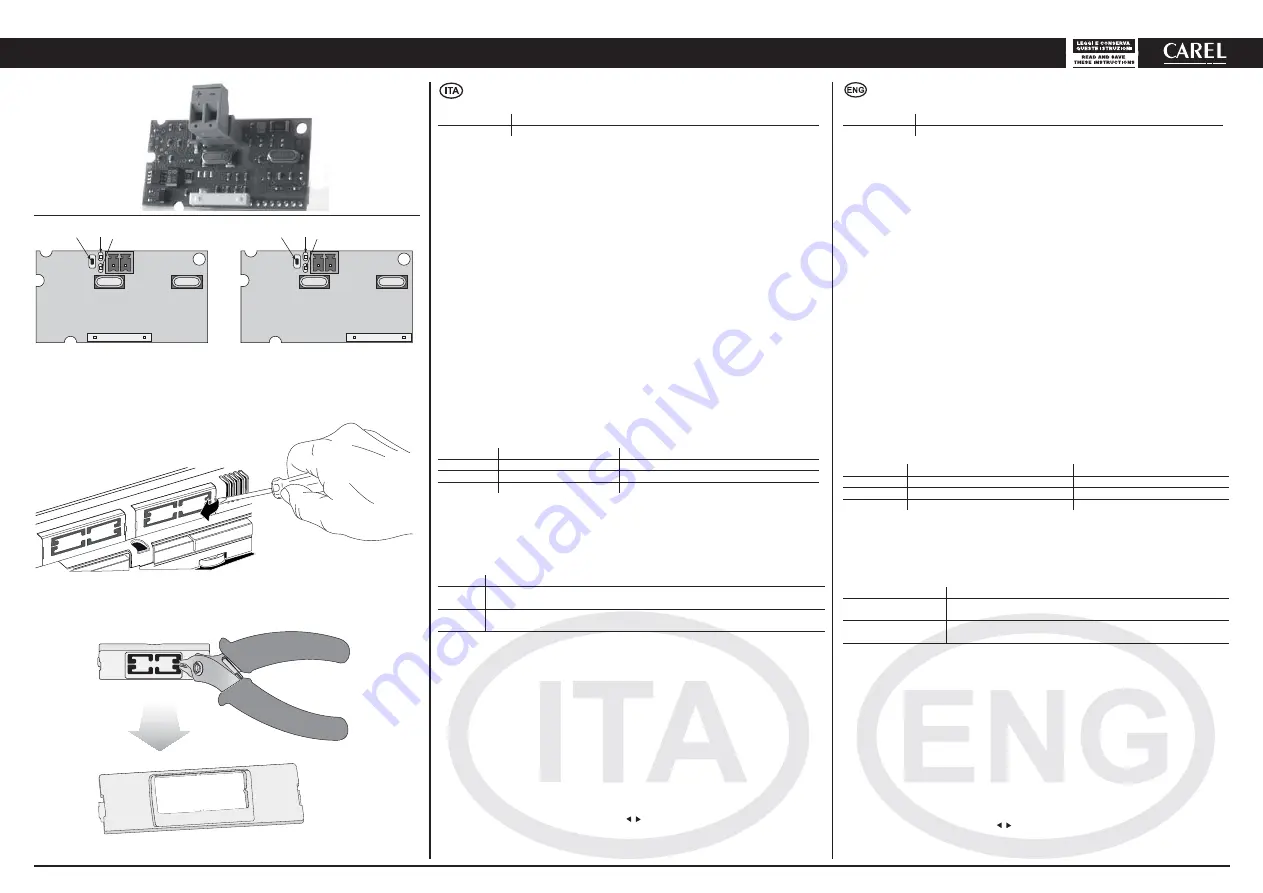
Montaggio su pCO / Assembly on pCO
Fig 2
Fig 1
Fig 3
Red
Green
+
Green
+
-
-
Push button
PCOS00KXB0
PCOS00KXF0
Red
Push button
The PCOS00KX** electronic boards are optional devices that allow the pCO series and e-drofan
controllers to connect to a network operating on the Konnex standard.
PCOS00KXB
Model for the pCO BMS port, “Serial card” and e-drofan sockets
PCOS00KXF
Model for the pCO
3
Field-bus port, “Field card” socket
Assembly on pCO
With reference to Fig. 2-5, the card is installed on the pCO* when the unit is not powered, according to
the following procedure:
1. Use a screwdriver to remove the “serial card” or fi eld card cover, depending on the model of pCO (see
Fig. 2);
2. Use cutting nippers to remove the pre-cut plastic part from the cover, opening the hole required for the
output of the 2-pin connector (see Fig. 3);
3. Insert the optional card in the corresponding socket, making sure that the card is fi tted correctly and in
contact with the two supports on the case of the pCO (see Fig. 4).
Warning! The card and the connectors may be hard to install due to the space available and the two plastic
supports; the card should be inserted obliquely, and then rotated until the connectors are fi tted.
4. Close the cover again, lining up the connector on the serial card with the hole opened on the cover
(see Fig. 5).
Assembly on e-drofan
With reference to Fig 6, the card is installed on the e-drofan when the unit is not powered, inserting the
optional card correctly in the corresponding socket (Fig 6b). Hook and screw the plastic support (included
in the packaging) as in fi gure 6c and 6d.
Confi guration of the pCO and e-drofan communication parameters
pCO
e-drofan
Baud rate
9600 Baud
fi xed 9600 Baud
Address
1
P69=1
Protocol
Modbus
P54=1
Confi guration and connection to the Konnex network
The confi guration of the card requires the ETS3,
ETS4
software, the fi le CAREL-plugin-xx.pr4 and the KSet
tool (available at ksa.carel.com).
TOOL
Function
KSet
Association of Modbus
®
registers with Konnex datapoint
Assignment of group addresses for each datapoint
ETS3, ETS4
Assignment of device network address
Download .xlm fi le
Proceed as follows:
1) create a new project or open an existing project
2) import the project database called CAREL-plugin-xx.pr4
3) defi ne the group addresses for all the datapoints
4) From KSet: open or create a new xxx.XML fi le, defi ne the list of associations between KNX datapoints
and Modbus® registers, in the “groups” column enter the group addresses set using ETS3,
ETS4
of the
datapoints to be shared and, at the end, save the confi guration (.xml fi le)
5) From ETS3,
ETS4
: a) Open ETS3,
ETS4
and add the CAREL devices
b) Assign the address to each device using the standard procedure (pressing the button
on the card - see Figure 1).
Confi gure the card by downloading the .XML fi le saved previously (from the Properties menu on the plug-
in, select CAREL device confi guration use to display the menu).


