

1. Configuration Flowchart
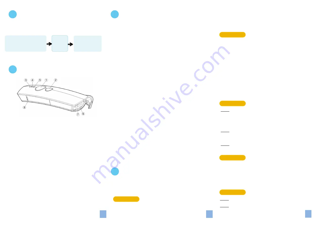
2. Product Overview
3.
Einstellen
Scanners
des
3-1. Operation Mode
3-2. Output Interface in Cable mode
After scanning
Enter
barcode, specify which output interface
the device works with in Cable mode.
4. Basic Scanner Operations
You can perform most of below basic operations by either
scanning the barcode sequences or using the button triggers.
4-1. Mode Switch
Button Trigger
Keep holding Scan Button till the LED light turns from a rapidly
blinking color into a solid color. After a release of Scan Button,
you, by observing the LED light colors, can learn which
operation mode your scanner is switched to.
Scan Sequence
After reading
ENTER
label, scan the below appropriate
barcode to switch to the desired operation mode.
4-2. Transmit all barcode data
Button Trigger
Step 1
Secure the interface cable to both the barcode reader
and the Host PC Open the preferred word processing
software to receive the scanned data.
Step 2
After holding Small Trigger long enough to trigger off a
solid LED light, release Small Trigger.
Step 3
While the orange LED starts flashing rapidly, press Scan
Button once again to transmit all barcode data.
Scan Sequence
Scan
Data Memory Tx
barcode after reading
Enter
label.
4-3. Clear all saved barcode data
Button Trigger
Step 1
Configure the scanner to be in Memory mode.
Step 2
While holding Small Trigger till orange LED starts
*A40C3*
Bluetooth
*A40C2*
Cable+Mem
*A40C4*
Cable+BT
*A40C5*
Mem+BT
*A40C6*
Cable+Mem+BT
*B21D1*
USB HID
*B21D2*
USB COM
*B21D3*
RS232
*ZTOS*
To Cable Mode
*ZTOM*
To Mem Mode
*ZTOB*
To BT Mode
*ZMTX*
Data Memory Tx
○
1
Press
Scan Button
to read barcodes.
○
2
Press
Small Tirgger
to perform supplementary fucntions.
○
3
Good Read Indicator
indicates whether the barcode is
decoded. Green LED shows a successful decodeing attempt.
○
4
Mode Indicator
indicates the current operation mode status.
Blue LED stands for Bluetooth mode, green LED for Cable mode,
and orange LED for Memory mode
○
5
Power Indicator
indicates the battery charge status.
when the battery is running low, red LED light will be on
to show a poor charge level. Once the charging
process is completed, red LED will flash slowly to show
a full battery charge.
○
6
Strape Hole
○
7
Secure the interface cable into
USB Port
to charge the
battery or transmit data.
○
8
Replace the battery in the
battery compartment
.
desired
barcodes
ENTER
barcode
*/$%ENTR*
END
barcode
*ZEND*
Please make sure you always start a scan sequence with
ENTER
barcode and end with
END
barcode as a successful attempt.
We offer a selection of mode combinations, including 3 in1
functions, for your convenience to improve efficiency at work.
Before reading the below barcodes, please scan
Enter
label first to
ensure a successful configuration.
2
1
3
*A40C0*
Cable
*A40C1*
Memory


