background image

Documentazione

Tecnica

S45

rev.  

2.2

07/2002

©

 CAME

CANCELLI

AUTOMATICI

FROG A

CANCELLI AUTOMATICI

SCHEDA


COMANDO

CONTROL


BOARD

CARTE


DE


COMMANDE

STEUERPLATINE

TARJETA


DE


MANDO

I

T

ALIANO

/

ENGLISH

/

ESP

AÑOL

119AS45-1

SERIE

 FROG 

|  

FROG 

SERIES

  | 


SERIE

 FROG

8

6

5

2

4

7

10

9

3

1

9

1

10

3

4x1,5

3x1,5

230V

4x1

2x1,5

RG58

3x1

5x1

2x1

4x1

RX

TX

RX

TX

4x1,5

2x1

11

10

1   -

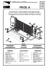
Gruppo  FROG

2   -

Quadro  comando  incorporato

3   -

Fotocellule  di  sicurezza

4   -

Ricevitore  radio

5   -

Selettore a chiave

6   -

Antenna  di  ricezione

7   -

Pulsantiera  interna

8   -

Lampeggiatore  di  movimento

9   -

Colonnina  per  fotocellula

10 -

Scatola di derivazione per cavo
motoriduttore (é consigliabile fare le
connessioni del cavo
motoriduttore in scatole di deriva-
zione)

11 -

Trasmettitore  radio

Impianto tipo

Instalación tipo

1   -

Conjunto  FROG

2   -

Cuadro  de  mando  incorporado

3   -

Fotocélulas  de  seguridad

4   -

Radiorreceptor

5   -

Selector  mediante  llave

6   -

Antena  receptora

7   -

Pulsadores  de  interior

8   -

Lámpara  intermitente  de  movimento

9   -

Columna  para  fotocélula

10 -

Caja de paso para el cable del
motorreductor (se aconseja hacer las
conexiones del cable del
motorreductor en cajas de paso)

11 -

Transmisor

Standard installation

1   -

FROG  unit

2   -

Control  panel  (incorporated)

3   -

Safety  photocells

4   -

Radio  receveir

5   -

Key-operated  selector  switch

6   -

Antenna

7   -

Internally  located  pushbutton  arry

8   -

Flashing light

9   -

Photocell column

10 -

Connector block for gearmotor cable (it is
advisable to make gearmotor cable
connections within connector blocks).

11  -

Radio  transmitter


Automazione per cancelli a battente (montaggio interrato)


Automatic opening system for wing gates (underground installation)

     Automatizacion para puertas batientes (montaje en el terreno)

Cables de alimentación motores:

2 x 1.5 mm

2

 hasta 20 m

2 x 2.5    "      "    30 m

Cables de conexión microinterruptores:

3 x 1mm

2

Power wires to motor:

2 x 1.5 mm

2

 up to 20 m

2 x 2.5 mm

2

 up to 30 m

Wiring for microswitches:

3 x 1 mm

2

Cavi di alimentazione motori:

2 x 1.5 mm

2

 fino a 20 m

2 x 2.5 mm

2

 fino a 30 m

Cavi di collegamento microinterruttori:

3 x 1 mm

2

FROG A24

Summary of Contents for FROG series

Page 1: ...sadores de interior 8 L mpara intermitente de movimento 9 Columna para fotoc lula 10 Caja de paso para el cable del motorreductor se aconseja hacer las conexiones del cable del motorreductor en cajas...

Page 2: ...per montaggio interrato in cassa di fondazione FROG B FROG BI Progettato e costruito interamente dalla CAME Cancelli Automatici S p a Grado di protezione IP 67 Garantito 24 mesi salvo manomissioni Ve...

Page 3: ...s de mando de seguridad y los acesorios sean originales CAME lo cual garantiza y facilita el uso y el mantenimientodelaparato Caracter sticasGenerales Regolabile mediante quadri comando CAME Servizio...

Page 4: ...r drainage to avoid rust causing conditions Fig 3 part 1 The foundation box simplifies and speeds up the installation of the unit install it inside the trench with the stud aligned with the top hinge...

Page 5: ...Sujete el motorreductor a la caja de ci mentaci n mediante los pernos rosca dos y bloque ndolo con las tuercas y arandelas suministradas Introduzca el brazo de transmisi n C entre el brazo motor y la...

Page 6: ...veta de enganche del desbloqueo Fig 5 B det 3 para el procedimiento de desbloqueo refi rase a la documentaci n de cada ar t culo N B las operaciones de desbloqueo se realizan en las maniobras de emerg...

Page 7: ...ci n de las respec tivas tarjeta electr nicas de mando ZA3 ZA4 ZA5 o ZM2 R1 Ra1 Microinterruttore di rallentamento motore 1 in apertura Microswitch deceleration of motor 1 on aperture Microinterruptor...

Page 8: ...N 50081 1 AND 2 ELECTROMAGNETIC COMPATIBILITY EN 50082 1 AND 2 ELECTROMAGNETIC COMPATIBILITY IMPORTANT CAUTION It is forbidden to market use product s that are the subject of this declaration before c...

Page 9: ...io 5 S lecteur a cl 6 Antenne de reception 7 Poussoir interne 8 Clignotant de mouvement 9 Colonne pour photocellule 10 Bo te de derivation pour c ble du motor ducteur il est conseill d effectuer les c...

Page 10: ...n V rifiez que l appareillage de commande de s curit et les accessoires sont des produits originaux CAME afin de garantir l instal lation et d en faciliter le montage et l entretien FRAN AIS Caract ri...

Page 11: ...dem Tor max 2 m breite T rflugel Bei der Ausf hrung FROG A24 Kann FL 180 nicht montiert werden Elektrische Schlie anlage mit Einzelzylinder Elektrische Schlie anlage mit Doppelzylinder FROGA24 FROG A...

Page 12: ...F r guten Wasserabflu8 sorgen um Stauungen und daraus erfol gende Oxydierungen zu vermei den Abb 3 Teil 1 Der Fundamentkasten vereinfacht die Fundamentierung den Kas ten in die Grube stellen den Zap f...

Page 13: ...r en regeling van de overbrengingsarm Installation vom getriebemotor und einstellung vom antriebsarm Draai de schroef M10 x 100 A en de moer M10 B in de arm van de motor zoals afge beeld op fig 4 1 re...

Page 14: ...en Eindeloop openen plaatsen Fig 6 Plaats de microschakelaar onder de magneet Fig 7 De vleugel op ongeveer 100mm van de eindeloop sluiten plaatsen en de micro schakelaar instellen De tweede microschak...

Page 15: ...eschwindigkeitsverz gerung Mofor 1 beim ffnen R1 Rc1 Microinterrupteur ralentissement moteur 1 dans la phase de fermeture Microswitch vertraging motor 1 in sluitings fase Mikroschalter Geschwindigkeit...

Page 16: ...t 15 31030 Dosson di Casier Treviso ITALY tel 39 0422 4940 fax 39 0422 4941 internet www came it e mail info came it verklaren onder eigen verantwoordelijkheid dat het product de producten met naam co...

Reviews: