


Installation
P.O. Box 309
Menomonee Falls, WI 53052 USA
800 BRADLEY (800 272 3539)
+1 262 251 6000
bradleycorp.com
215-1890 Rev. E: ECO 20-08-028A
© 2020 Bradley
Page 1 of 24
10/29/2020
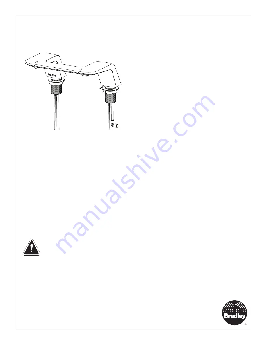
WBD1
WashBar
™
Duo
Table of Contents
Safety Information .............................................................2
Supplies Required .............................................................2
Components ...................................................................3-5
Dimensions .....................................................................6-9
Structural Rough-Ins ........................................................10
Plumbing and Electrical Rough-Ins .................................11
WashBar Installation ........................................................12
Aerator Installation ...........................................................12
Attach Soap Motor and Soap Container Bracket ............13
Control Box and Valve Installation .............................14-15
Soap Installation ..............................................................16
Electrical Connections .....................................................17
Adjust Temperature with Water Running .........................17
Master Control Box .....................................................18-22
Cleaning and Maintenance .........................................23-24
Read the instructions in this manual before beginning installation. Save these instructions and refer to
them for inspection, maintenance, and troubleshooting information.
For questions regarding the operation, installation or maintenance of this product, visit bradleycorp.com or call 800.BRADLEY (800.272.3539).
Product warranties and parts information may also be found under “Resources” on our website at bradleycorp.com.


