WimTec Proof W6 113 792, Assembly And Operating Instructions Manual
Introducing the WimTec Proof W6 113 792 - a high-performance product designed to simplify your daily tasks. Our Assembly And Operating Instructions Manual offers step-by-step guidance, ensuring easy setup and efficient use. Download this essential manual for free from manualshive.com. Discover the full potential of your product now!
Share
Download


Reviews:
No comments
Related manuals for Proof W6 113 792
6068
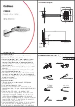
Brand: Ca'Bano Pages: 4
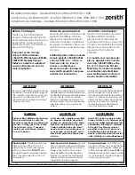
W24
Brand: Zenith Pages: 2

Zimi 1-116-8500-00
Brand: ADF Pages: 4

360 9G5S Series
Brand: Artweger Pages: 32

ELEGANCE ESKK2 80
Brand: RAVAK Pages: 12

QL0322
Brand: Transform Pages: 26

KN-II/EKOPLUS /185
Brand: SANPLAST Pages: 12

25702LF
Brand: Delta Pages: 6

KTS13-TC
Brand: Luxier Pages: 4

Metris C 31075 1 Series
Brand: Hans Grohe Pages: 16

Metropol 32556 1 Series
Brand: Hans Grohe Pages: 20

Logis Fine 240 71258 1 Series
Brand: Hans Grohe Pages: 16

Marin2 Vario 28378000
Brand: Hans Grohe Pages: 20

Showerpipe EHM EcoSmart 27191000
Brand: Hans Grohe Pages: 40

S 04231000
Brand: Hans Grohe Pages: 24

Metris M71 320 1jet 73812 Series
Brand: Hans Grohe Pages: 48

Pharo Duschtempel 100 Quadra ML40L 29 36...
Brand: Hans Grohe Pages: 56

Talis Select M51 220 2jet
Brand: Hans Grohe Pages: 40


