Body Solid GDR80, Assembly Instructions & Owner'S Manual
The Body Solid GDR80 is a versatile and dependable weight rack designed to help you stay fit and organized. With its robust construction and user-friendly features, this outstanding fitness equipment is perfect for any home gym. For your convenience, you can easily access the Assembly Instructions & Owner's Manual for free download from our website, ensuring a hassle-free setup experience.
Share
Download


Reviews:
No comments
Related manuals for GDR80

TL32833
Brand: Costway Pages: 4

18816
Brand: K&M Pages: 4

CP-WALLPLATE-5
Brand: Alula Pages: 2

Neomounts PLASMA-M1700ES
Brand: NewStar Pages: 8

KZ715AS
Brand: Kilsen Pages: 12

BJ-EX1
Brand: BJ Live Pages: 10
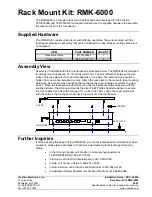
RMK-6000
Brand: Crestron Pages: 2

VisionMount VLF210
Brand: Sanus Pages: 36
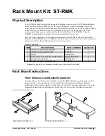
ST-RMK
Brand: Crestron Pages: 4

MSHWL Series
Brand: Displays2go Pages: 3

M40322
Brand: Carolina Cooker Pages: 28

SQM7441
Brand: Philips Pages: 2

SQM7842
Brand: Philips Pages: 2

SBC VS010
Brand: Philips Pages: 12

SQM5572/27
Brand: Philips Pages: 23

TS218SU
Brand: CHIEF Pages: 16

92725
Brand: Thule Pages: 7

1555
Brand: Thule Pages: 8


