Body flex BRD 2800, Owner'S Manual
The Body Flex BRD 2800 is a versatile workout equipment designed to enhance your fitness routine. To get the most out of this product, make sure to download the comprehensive Owner's manual for free at manualshive.com. The manual provides detailed instructions and exercises to achieve your fitness goals with ease.
Share
Download


Reviews:
No comments
Related manuals for BRD 2800

DX2
Brand: Diadora Pages: 79

93296
Brand: Life Gear Pages: 21

9823
Brand: Christopeit Sport Pages: 52

1827
Brand: Christopeit Sport Pages: 60

1420
Brand: Christopeit Sport Pages: 76

JR1+
Brand: Cubii Pages: 26

Premium 8
Brand: Daum electronic Pages: 40

ego_bike Premium 8
Brand: Daum electronic Pages: 44
Pro-Form PFIVEL86113.0
Brand: ICON Health & Fitness Pages: 20
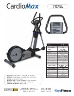
CardioMax 707 Elliptical CM707EL
Brand: Keys Fitness Pages: 1

CardioMax 708EL
Brand: Keys Fitness Pages: 20

PFEL04211.7
Brand: Pro-Form Pages: 28

G930BM
Brand: BH FITNESS Pages: 30

LK500E
Brand: BH FITNESS Pages: 36

X6600HRT/DA
Brand: Vision Fitness Pages: 8

F7 Fold Away Strength Trainer
Brand: Torque Fitness Pages: 48

520 Reclined Elliptical
Brand: Schwinn Pages: 32

Techness SE 400
Brand: Tool Fitness Pages: 97


