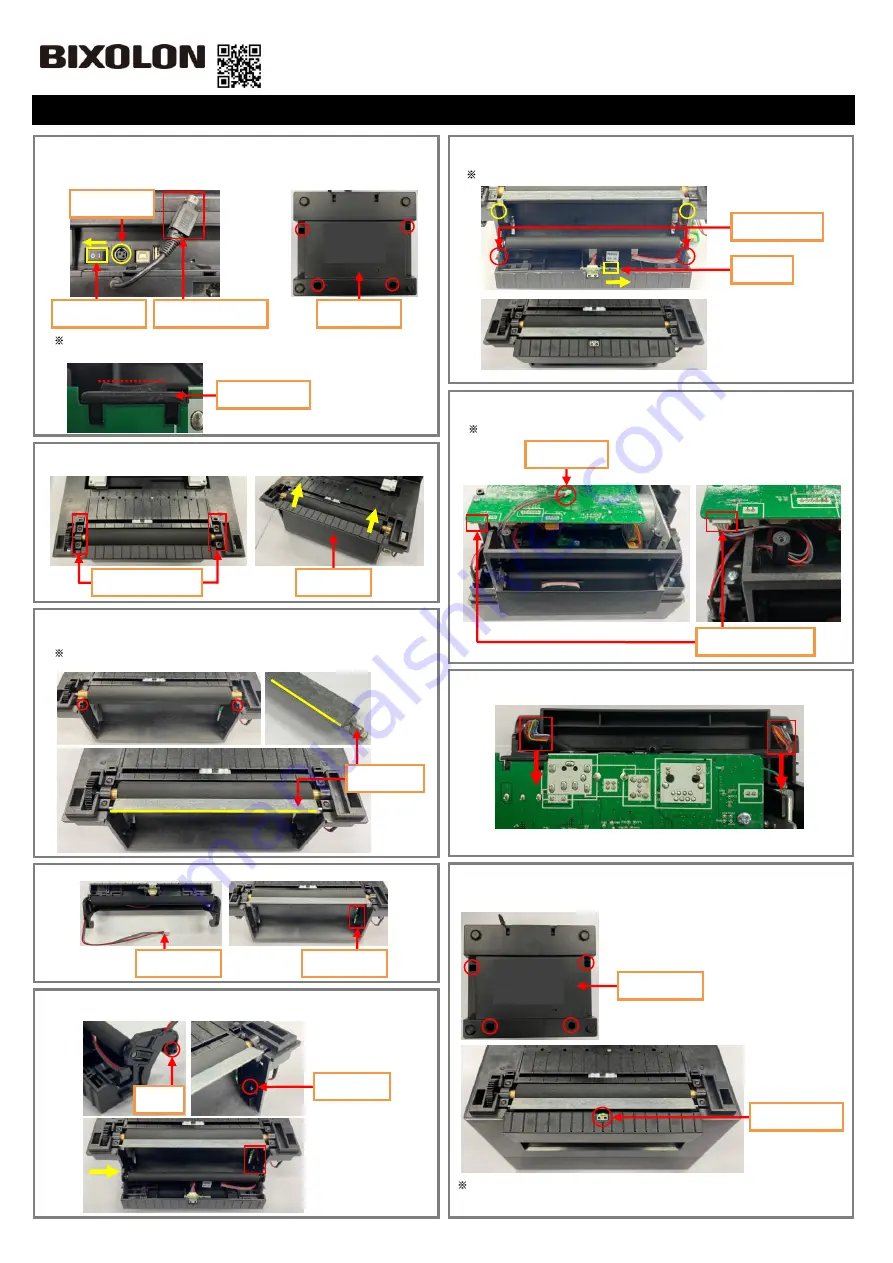
1. After the Power Switch Off at the rear of the Printer, Unplug the Power
Connector from the Power Jack. Place the bottom of the Printer face the
front. Remove four screws (in Red circle) using a screwdriver and
disassemble the Case Lower.
When disassembling the Case Lower, disassemble it while keeping the
Power Switch in a horizontality. (As a red dotted line).
2. Open the Printer. After disassemble the Cover Roller L&R, Disassemble
the Cover STD upwards (Yellow arrow).
3. Assemble the Peeler Bar by aligning the direction to the square hole
below(Red Circles).
Then, reassemble the Cover Roller L&R that was removed in step 2.
Be careful to install the Peeler Bar correctly. Otherwise, the Peeler will not
work properly.
4. Insert the Peeler Wire into the Wire Hole.
5. With the Wire inserted, fit the right Boss of the Peeler to the Boss Hole as
shown below. Also, fit the left one to the Boss Hole.
6. Turn the Switch On as shown below. Then, engage the Peeler Levers with
the sockets (yellow circles) to close so that they make a clicking sound.
If the Levers are not engaged correctly, try again after repeating steps 4 and 5.
7. Place the bottom of the Printer face the front.
Insert the Peeler Wire to the
Peeler Connector (red square) in the correct direction.
Be careful to avoid tangling with other wires when shaping.
8. Put the wires (Two red squares) inside as much as possible.
9. Reassemble the Case Lower that was removed in step 1. Then, connect the
power supply and turn the power on to check if the Peeler Sensor LED is
green when turned on.
See the User Manual for how to supply paper.
How to Mount Peeler
KN04-00211A (Ver.1.0)
SLP-DL410 Series
Off
Power Switch
Power Jack
Power Connector
Case Lower
Power Switch
Cover Roller L&R
Cover STD
Front
Front
Peeler Bar
Peeler Wire
Wire Hole
Boss
Boss Hole
On
Switch
Peeler Lever
Peeler Wire
Peeler Connector
Case Lower
Peeler Sensor