Bell System 4A, Identification, Installation, Connection, Operation, And Maintenance Customer Equipment
Get the Essmann 4A Technical Information and Operating Instruction manual for free download on our website. This comprehensive manual covers every aspect of the product, providing users with step-by-step instructions and technical details. Visit our website to access this valuable resource and enhance your understanding of the Essmann 4A product.
Share
Download


Reviews:
No comments
Related manuals for 4A

IG-02
Brand: ICM Controls Pages: 2

BP600
Brand: Balboa Pages: 23

HCS-3900 series
Brand: Taiden Pages: 55

Reflex Wheel-X 50 050 0030
Brand: Carson Pages: 52

HCS-4393G2
Brand: Taiden Pages: 19

CSS205
Brand: RAM Pages: 36

EliteIQ
Brand: Cattron Pages: 72

DOCKCONTROLLER DC-200
Brand: Motorola Pages: 16

HP 4062F
Brand: HP Pages: 174

7 620 320 024
Brand: Bosch Pages: 252

L-force PROFINET E94AYCER
Brand: Lenze Pages: 114

KD-SX8350
Brand: JVC Pages: 32

KD-SX995
Brand: JVC Pages: 45

KD-X151
Brand: JVC Pages: 72

KD-SX8350
Brand: JVC Pages: 71
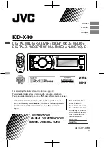
KD-X40
Brand: JVC Pages: 56

KD-SX995
Brand: JVC Pages: 81

KD-X30
Brand: JVC Pages: 82


