Banner IVU BCR Series, Instruction Manual
The "Banner IVU BCR Series" Instruction Manual is available for free download on our website. Obtain step-by-step guidance and comprehensive information on operating and troubleshooting this exceptional product. Simply head to manualshive.com to access the manual and unlock the full potential of your Banner IVU BCR Series.
Share
Download


Reviews:
No comments
Related manuals for IVU BCR Series

epos
Brand: Tolino Pages: 79

PCUSBGO2
Brand: Velleman Pages: 19

1524-331
Brand: DoorKing Pages: 3

IDM160
Brand: Stahl Pages: 36

NFT 1125 Series
Brand: Opticon Pages: 61

Cobalto CO5330
Brand: Datalogic Pages: 292
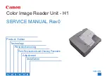
H1
Brand: Canon Pages: 112

RP350x
Brand: TSYS Pages: 83

Kiosk II
Brand: VIVOpay Pages: 19

ViewPad 7e
Brand: ViewSonic Pages: 2

602
Brand: Ier Pages: 17

1005294
Brand: Viking Pages: 20

MIFARE Classic AY 5B Series
Brand: Rosslare Pages: 2

AYC-Q6355
Brand: Rosslare Pages: 69

Mifare CP-R25
Brand: Rosslare Pages: 52

OPI-2101
Brand: Opticon Pages: 4

M260
Brand: E-Seek Pages: 16

iDC9508K
Brand: RIOTEC Pages: 6


