


1
INSTRUCTION MANUAL
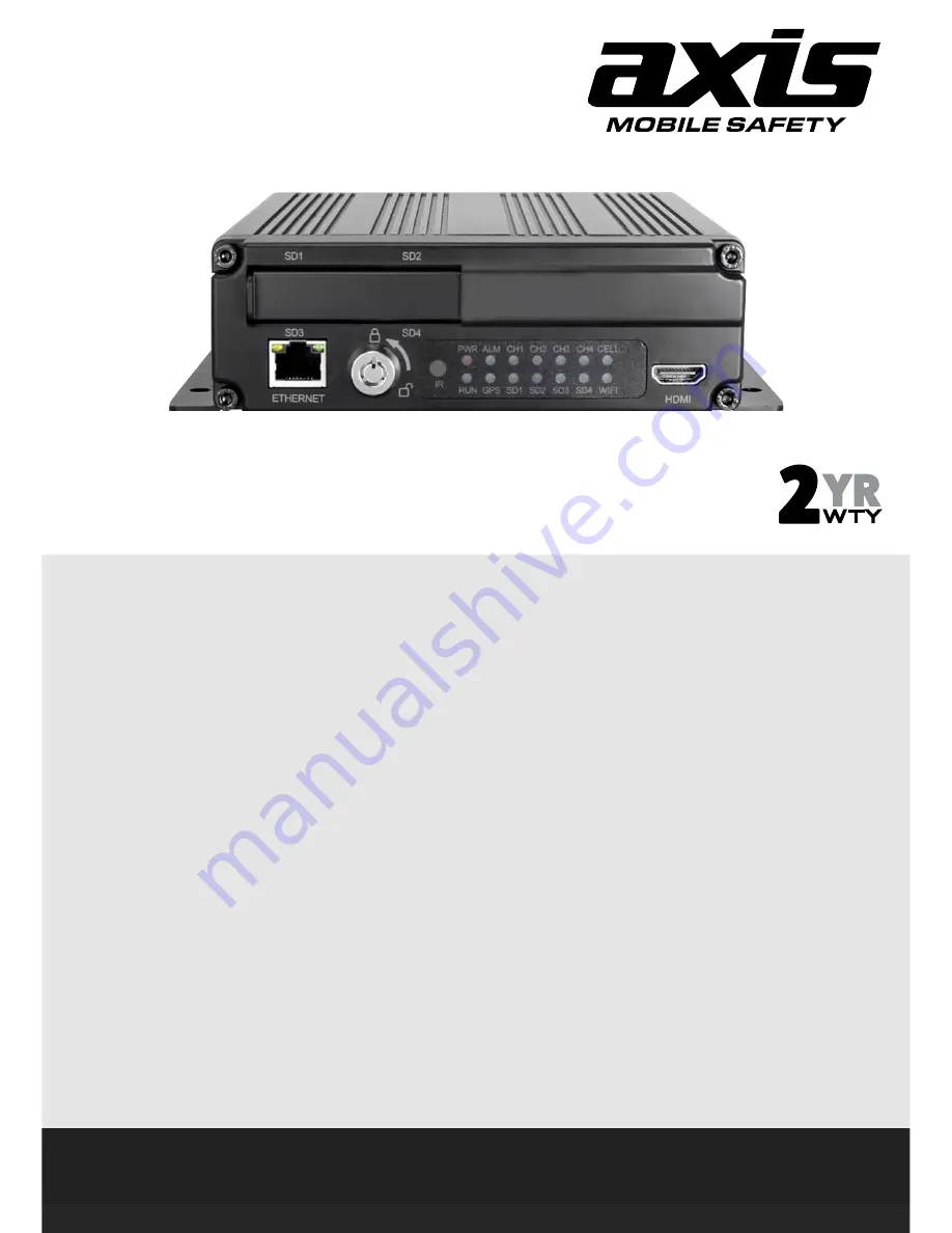
DV425/DV425GPS
4CH HD BLACK BOX RECORDER with WiFi
SPECIFICATIONS
- Record Type:
Quad
-
GPS:
Yes
(DV425GPS)
-
WiFi:
Yes
- Max Resolution:
1920 x 1080 (100FPS)
- Max Card Supported:
4 x 128GB MLC Type
- Card Type:
SD/SDHC/SDXC cards
- Continuous Recording (Approx):
76 Hours 4 x 1080P @ 4Mbps
- Real Time Recording:
Yes - Auto or Scheduled
-
G-Sensor:
Yes
- Motion Detection:
Yes
- Recording Output:
USB & HDD Video Recording & Backup
- AV Output:
Touchscreen Compatible HDMI, 2 x CVBS
(RCA & 6 Pin)
- Monitor View:
Normal/Mirror Image Selectable
- Video Compression:
H.264 for High Quality Video
- Reverse Camera Compatible:
Yes, compatible with systems that have motorized
cameras and adjustable grid lines
- Camera Connection:
4-Pin
- Lockable SD Cards:
Yes
- HDD Support:
Up to 2TB HDD
- Operating Voltage:
9 to 36V
- Alarm Inputs:
8 CH
- Alarm Outputs:
2 CH
- Ignition Signal:
Yes
- Speed Signal:
Yes
- Timer Recording:
Yes
- Adjustable Frame Rate & Bit Rate:
Yes
- Individual Camera Adjustment:
Contrast, Hue, Brightness, Colour
- User Password Protection:
Yes
- Operating Temperature:
-20°C to 70°C
- Power Consumption:
15W (Working)
- Dimensions:
178W x 50H x 171Dmm
INCLUDED
- Lock Key
- Remote Control
- GPS Antenna (DV425GPS)
- 6P to 4P A/V Conversion Cable
- 3V Out Cable for External GPS
- 4 Pin (Female) to 4 Pin (Female) Fly Lead
- Installation Manual
- Installation Hardware
Summary of Contents for DV425
Page 25: ...25 5 7 Volume Modulation 0 is the minimum volume and 10 is the maximum volume 6 Record Setup ...
Page 37: ...37 7 9 Mirror ON Turn on Mirror function OFF Turn off Mirror function 8 Network ...
Page 43: ...43 8 5 FTP ...
Page 44: ...44 9 System 9 1 Log in Setup Set user name and password for boot up ...
Page 45: ...45 9 2 License Plate Number Setup Set license plate number and IP number ...
Page 47: ...47 9 5 Exception 9 6 ACC Settings ...
Page 55: ...55 9 10 System Info System Info Software version number ...
Page 58: ...58 12 NOTES ...
Page 59: ...59 ...
Page 60: ...60 DV425 DV425GPS ...


