


The information contained in this document is the pro perty of Automatic Systems and is confidential. The recipient shall
refrain from using it for any purpose other than the use of the products or the execution of the project to which it refers a nd
from communicating it to third parties without written prior agreement of Automatic Systems
.
RSB76E-MT-EN
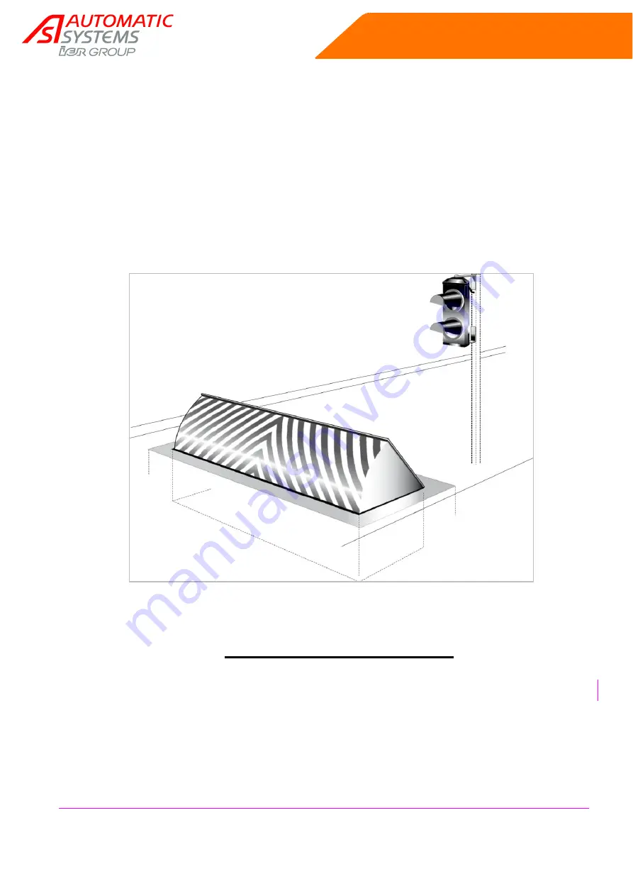
RSB 76E
RISING STEP BARRIER
RSB 76E
TECHNICAL MANUAL
(Translated from French original notice)
Rev 11


