Audio Technica 5000 Series, User Manual
The Bosch 5000 Series is a high-performance appliance designed to elevate your cooking experience. With our user-friendly manual packed with Quick Tips, you'll master its advanced features effortlessly. Download the free manual from our website manualshive.com, and unlock the full potential of your Bosch 5000 Series appliance.
Share
Download


Reviews:
No comments
Related manuals for 5000 Series

DTM Series
Brand: W Audio Pages: 12

GuestCall
Brand: JTECH Pages: 2

LS-902
Brand: Azusa Pages: 20

OmniBER J7230A
Brand: Agilent Technologies Pages: 174

577B
Brand: Shure Pages: 2

CO2 Monitor 2800
Brand: Bacharach Pages: 16

RS2050
Brand: RCA Pages: 19

WHD3
Brand: Knoll Pages: 2

pb360c
Brand: Bosch Pages: 40

Plena LBB 1970
Brand: Bosch Pages: 21

Praesideo 3.5
Brand: Bosch Pages: 498

CA-UXQD90B
Brand: JVC Pages: 56

CA-UXP3
Brand: JVC Pages: 41

CA-UXG55
Brand: JVC Pages: 48

CA-UXS11
Brand: JVC Pages: 74

CA-UXP7R
Brand: JVC Pages: 28
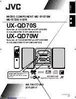
CA-UXQD70S
Brand: JVC Pages: 82

CA-UXN1S
Brand: JVC Pages: 31


