background image

Installation Guide

AT-VTP-800

1

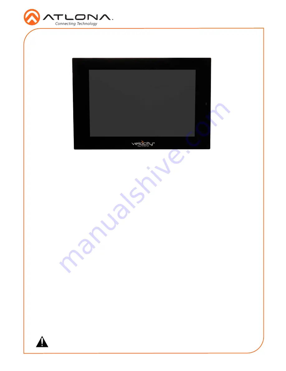
Velocity 8” Touch Panel

AT-VTP-800

1 x AT-VTP-800

1 x Metal mounting plate

4 x Mounting screws

1 x Wall installation template

1 x 2-gang mud ring

1 x Installation Guide

Package Contents

Operating Notes 

• 

The Velocity 8” Touch Panel (AT-VTP-800) must be on the same network as the Velocity 

Gateway (AT-VGW-250) or it will be unable to sync for control.

• 

The AT-VTP-800 is PoE capable, to power the unit, simply plug it into a 802.3at compatible 

network switch. If the network switch is not PoE capable, a PoE injector 

(purchased separately)


can be used.

IMPORTANT

: Velocity Gateway (AT-VGW-250) must be set up before the AT-VTP-800 is 

fully functional.

The Atlona AT-VTP-800-BL and AT-VTP-800-WH are 8” touch panels in black and white, 

respectively, for the Atlona Velocity™ Control System. They feature contemporary, refined styling 

for modern presentation environments with 1280x800 native resolution, and a capacitive glass 

surface that supports multi-touch and gesture interactions. These touch panels conveniently 

install into a wall or furniture via a US two-gang opening. Also available is the optional AT-VTP-

TMK tabletop mounting kit for placement on a meeting table or lectern. The VTP-800-BL and 

VTP-800-WH feature Power over Ethernet (PoE), enabling a single network connection for data 

and power. Setting up the touch panels is effortless as the AV control GUI is automatically 

uploaded from the Velocity Control Gateway processor during system configuration.

Summary of Contents for Velocity AT-VTP-800-BL

Page 1: ...T VTP 800 is fully functional The Atlona AT VTP 800 BL and AT VTP 800 WH are 8 touch panels in black and white respectively for the Atlona Velocity Control System They feature contemporary refined styling for modern presentation environments with 1280x800 native resolution and a capacitive glass surface that supports multi touch and gesture interactions These touch panels conveniently install into...

Page 2: ...l mounting plate into the mud ring using the 4 included screws 4 Remove the two screws from the bottom of the touch panel 5 Run the Ethernet cable through the mud ring and metal mounting plate 6 Connect the Ethernet and or power cable into the back of the touch panel 7 Line up the touch panel with the mounting plate and thread the metal hooks into the four holes on the back of the panel 8 Gently p...

Page 3: ... using the four stand screws included in the stand box a Thread the screws through the 4 pre drilled holes in the front of the stand into the four screw holes on the back of the touch panel NOTE Tight the screws by hand To avoid damage to the touch panel do not overtighten Installation and Set Up 1 Connect the Ethernet cable into the back of the unit a If the Ethernet cable is connected to a non P...

Page 4: ...Static IP slider b Assign the unit a static IP Ensure there are no other devices on the network with the same IP to avoid connection issues 5 The unit will load a new screen Change the Device Alias if needed to help differentiate when there are multiple touch panels at a site 6 Press the SCAN FOR GATEWAYS button Velocity Device Setup Device Alias URL 0 0 0 0 Velocity Touch Panel 800 SCAN FOR GATEW...

Page 5: ...s the Synchronize button on the touch panel s room 12 Press the SAVE CONTINUE button on the touch panel Velocity Device Setup Device Alias URL 10 0 0 234 Velocity Touch Panel 800 SCAN FOR GATEWAYS SAVE CONTINUE BACK 13 Depending on the room options there may be multiple buttons on the home page Select the any icon to open the room s control page 14 Select sources and displays by tapping on them a ...

Page 6: ...net Mask Default Gateway DNS Server 75 75 75 75 10 0 0 1 255 255 255 0 10 0 0 123 URL Gateway Settings Device Settings Touch Screen LAN Configuration 0 0 0 0 Alternate URL 0 0 0 0 Alias Velocity Touch Panel 800 SAVE FACTORY RESET CLEAR CACHE SCAN NETWORK CANCEL SET PIN Changing advanced settings requires application restart OK Within the advanced settings all the touch pad settings can be changed ...

Page 7: ...ting the Set Static IP slider and providing IP subnet gateway and DNS server information Connection Diagram ETHER NET HDMI OUT MDP OUT DC 19V 1 2 AT VGW 250 ETHER NET HDMI OUT MDP OUT DC 19V 1 2 AT VGW 250 E t h e r n e t P o E E t h e r n e t P o E E t h e r n e t P o E E t h e r n e t P o E E t h e r n e t P o E C o n t r o l AT VGW 250 AT VGW 250 redundancy Display E t h e r n e t E t h e r n e...

Page 8: ...Atlona Inc All other brand names and trademarks or registered trademarks are the property of their respective owners Pricing specifications and availability subject to change without notice Actual products product images and online product images may vary from images shown here Version 1 atlona com 408 962 0515 877 536 3976 ...

Reviews: