background image

8G.51.82.04 / 09.16  

Changes reserved. E.& O. E.

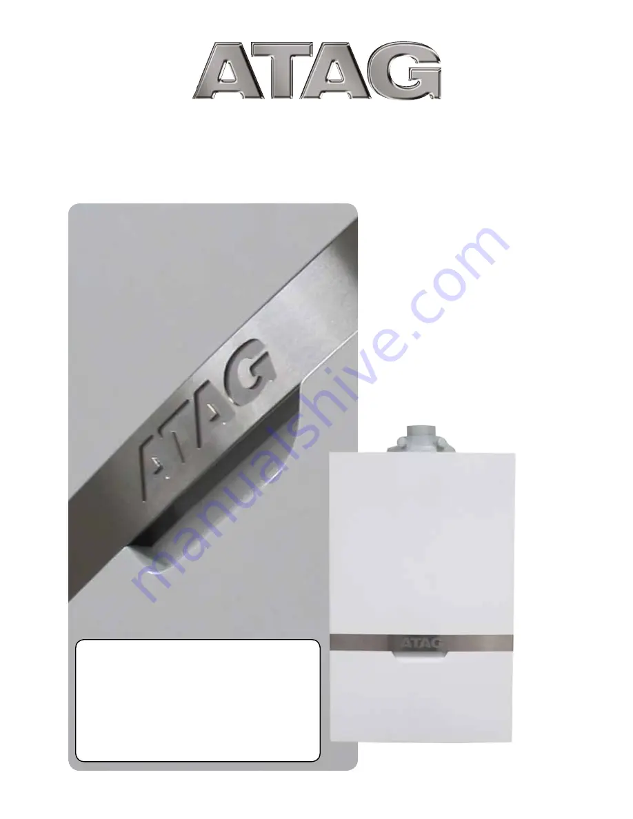
I n s t a l l a t i o n     &     S e r v i c i n g 

Instructions

These instructions are to be retained by the user.

Natural Gas Boilers

Boiler 

G.C No

iS 12 

41-310-18

iS 15 

41-310-20

iS 18 

41-310-22

iS 24 

41-310-24

iS 32 

41-310-26

iS 40 

41-310-28

Propane Gas Boilers

Boiler 

G.C No

iS 12 LPG 

41-310-19

iS 15 LPG 

41-310-21

iS 18 LPG 

41-310-23

iS 24 LPG 

41-310-25

iS 32 LPG 

41-310-27

iS 40 LPG 

41-310-29

CE PIN 0063CQ3634

iS


12

iS


15

iS


18

iS


24

iS


32

iS


40

Summary of Contents for IS 12

Page 1: ...user Natural Gas Boilers Boiler G C No iS 12 41 310 18 iS 15 41 310 20 iS 18 41 310 22 iS 24 41 310 24 iS 32 41 310 26 iS 40 41 310 28 Propane Gas Boilers Boiler G C No iS 12 LPG 41 310 19 iS 15 LPG 41 310 21 iS 18 LPG 41 310 23 iS 24 LPG 41 310 25 iS 32 LPG 41 310 27 iS 40 LPG 41 310 29 CE PIN 0063CQ3634 iS 12 iS 15 iS 18 iS 24 iS 32 iS 40 ...

Page 2: ... Press both buttons for 6 seconds Information on the water pressure The default view of the display shows OK Press the eco button for 6 seconds and press the scroll buttons until A6 is displayed The actual water pressure will be shown Water pressure too low Code 118 and spanner symbol visible Water pressure is too low 0 8 bar Power is reduced by 20 The installation should be refilled or Code 118 a...

Page 3: ...8 9 7 Condensation drain pipe 21 9 8 Flue gas exhaust system 25 9 8 1 Flue terminal locations 26 9 8 2 Dimensioning of the flue gas and air intake duct 29 9 9 Fitting the boiler onto the boiler frame 31 10 Electrical connection 33 10 1 One controller connections 34 10 2 Weather compensation connections 34 10 3 Electrical diagram 35 11 Filling system 36 12 Boiler controls 37 12 1 Controls and expla...

Page 4: ...ay into the installation instructions or user s manual Further ATAG reserves the right to alter its products without prior notification When delivering the boiler give the customer clear instructions concerning its use present the customer with the user s manual and warranty card Each boiler is fitted with an identification plate Consult the details on this plate to verify whether the boiler is co...

Page 5: ...ion commissioning and servicing work in accordance with the Benchmark Code of Practice which is available from the Heating and Hotwater Industry Council who manage and promote the Scheme Visit www centralheating co uk for more information The current Electricity at Work Regulation must be complied with and also be in accordance with the relevant and current editions of the British Standards The AT...

Page 6: ...red in these installation instructions and on the boiler packaging Boiler must be stored away from frost Protect packaging and or contents from damage as a result of insufficient care taken during transport Protect the boiler from weather conditions during transport and storage whilst still in its packaging If and how to clamp when using transport trucks with clamp equipment If and how to transpor...

Page 7: ...1 1 1 1 1 1 PMS Water pressure CH min max bar Flow temperature max C Pump type Available pump height CH kPa 25 25 25 25 20 20 SAP Annual Efficiency NG 89 8 89 8 89 8 89 8 89 8 89 8 CE product identification number PIN Technical specifications Propane gas Boiler type iS 12 iS 15 iS 18 iS 24 iS 32 iS 40 Heat exchanger type iCon1 iCon1 iCon1 iCon2 iCon2 iCon2 O2 at full load CO2 at full load Pre pres...

Page 8: ... 12 iS 15 iS 18 iS 24 iS 32 iS 40 Flue gas Air intake A B mm Gas connection mm CH Flow connection mm CH Return connection mm Condensate drain connection mm ATAG iS Series System 21 5 22 22 60 100 22 CH Flow CH Return Gas 700 150 850 220 225 60 220 380 440 137 343 A B B ...

Page 9: ...thought out principle using sustainable materials The boiler burns gas to supply heat natural gas and LPG versions available This heat is transferred in the heat exchanger to the water in the CH installation The rapid cooling off of the flue gases causes condensation This results in a very high efficiency The condensate that is formed has no negative impact on the heat exchanger and it s operation...

Page 10: ...el 9 Circulation pump 10 Flue gas exhaust 11 Combustion air supply 12 Boiler data plate 13 Expansion vessel 14 Safety valve 15 Siphon 16 Isolation valve flow CH T1 Flow sensor T2 Return sensor P1 Water pressure sensor ATAG iS Figure 7 a G Gas pipe A Flow pipe CH R Return pipe CH C Condensation pipe 17 Isolation valve gas 18 Isolation valve return CH T2 4 2 1 5 7 9 C G R 12 3 11 10 6 8 A 14 13 16 1...

Page 11: ...ble to fit a horizontal concentric flue system to the rear See chapter 9 8 for more flue options Make sure there is sufficient service space arround the boiler according figure 8 a The location of the boiler can be determined by using the template The wall frame allows the possibity to pre fit the complete heating system before fitting the boiler Also the flue system can be prepared Finally fittin...

Page 12: ...wall plug ø10x55mm in the holes Mount the boiler frame to wall with the 4 coach screws ø8x60mm using a 13mm wrench The boiler frame allows pipe work to be installed behind the boiler Note that there are free spaces on the left and right of the expansion vessel Do not guide pipe work in front of the expansion vessel The pipe work must be installed at least 10mm inside the front of the frame ATAG i ...

Page 13: ...cting to thick walled pipe welded or fitted adapters should be used The boiler has a self adjusting and self protecting control system for the load This involves checking the temperature difference between the flow and return water Table 9 1 a shows the water displacement the circulation pump can deliver for a particular installation resistance If the installation resistance is higher than the val...

Page 14: ... page 29 9 3 Water quality Fill the installation with mains cold water In most cases a heating system can be filled with water according to national standards for water and treatment of this water is not necessary In order to avoid problems with the CH installations the quality of the filling water has to meet the specifications mentioned in table 9 3 a If the filling water does not meet the requi...

Page 15: ...stallation and during additions or changes at a later stage ATAG Heating Technology Ltd recommends to keep a record of the type of water used its quality at the time and if applicable which additives and quantities were added Parameter Value Water type Potable water Softened water pH 6 0 8 5 Conductivity at 20 C in µS cm Max 2500 Iron ppm Max 0 2 Hardness dH ppm Installation volume capacity 20 l k...

Page 16: ...ontain dirt particularly with new pipes The complete installation MUST be tested for gas tightness and purged as described in the above code The boiler connection is provided with an isolation valve with 22mm compression fitting into which the gas line can be fitted 9 5 1 Natural gas connection NG The gas supply must comply to the current Gas Safety Installation Use Regulations in accordance with ...

Page 17: ...aximum permitted closing pressure may be 5 mbar higher than the maximum pre pressure A too high closing pressure in the low pressure gas line can be caused by a high resistance or jam in this gas line When the closing pressure keeps increasing the valve in the regulator is not closing correctly In this case the regulator should be replaced 9 5 4 Dimensioning of the low pressure gas line The gas li...

Page 18: ...erature sensor The cylinder sensor may be fitted into a sensor pocket if available please refer to the cylinder manufactures instructions If there is no sensor pocket as found with foam covered cylinders then the following steps should be followed 1 Mark a rectangular section of approximately 50mm w x 100mm h about one third of the cylinder height up from the bottom of the cylinder Caution Cut car...

Page 19: ...outside sensor ARZ0055U can be added to the 3 port diverter valve kit to sense the outside temperature specifically for the individual property The installation may require altered wiring of the dual thermostat depending on the cylinder the manufacturer to only use the high limit thermal cut out of the dual thermostat The high limit thermal cut out of the dual thermostat MUST be wired to interrupt...

Page 20: ...the 3 port diverter valve on the system pipework with the valve ports is the following orientation AB port iS System boiler A port hot water cylinder B port heating system a d c a b c B A AB AB B AB A B A a brown b blue c black d grey Junction box not included 3 port valve 230V AB iS System boiler A DHW Cylinder B Heating system ATAG outside sensor optional Cylinder sensor ATAG One controller 1 2 ...

Page 21: ...m waste pipe washing machine waste pipe etc A suitable permanent connection to the foul waste pipe should be used Figures 9 7 1 9 7 2 a 9 7 2 b show appropriate connection methods The possibility of waste pipes freezing downstream of the connection point should be considered when determining a suitable connection point e g a slightly longer pipe run to an internal soil stack may be preferable to a...

Page 22: ...condensate drainage pipe direct into gully 25mm min below grating but above water level end cut at 45 7 Sink lip 8 Minimum internal diameter 19mm fall at least 45mm per meter 9 Pipe size transition 10 Minimum internal diameter 30mm 11 Water weather proof insulation Drain requirements Figure 9 7 1 Drain requirements Figure 9 7 2 a Drain requirements Figure 9 7 3 1 Boiler 2 Visible air break at plug...

Page 23: ...nt guidance on condensate drainage pipe installation should also be followed Other cold weather protection methods approved or endorsed by boiler manufacturers and or service organisations may be adopted if these are considered suitable by the parties involved If an external soil vent stack is used as the external termination then the connection method shown in Figure 9 6 4 should be used together...

Page 24: ...rain requirements Figure 9 7 7 1 Boiler 2 Visible air break 3 38mm minimum trap 4 Visible air break and trap is not required because there is a trap with a condensate seal of 180mm incorporated into the boiler minimum requirement is 38mm 5 External length of pipe 3m maximum 6 Open end of condensate drainage pipe direct into gully 25mm min below grating but above water level end cut at 45 7 Minimum...

Page 25: ...onents of the flue gas and air supply system we recommend you consult the Flue system literature Combinations with other brands or systems are without written permission from ATAG Heating not permitted The ATAG flue gas system is meant and designed solely for the use on ATAG central heating boilers adjusted to Nat gas or LPG For this purpose the CE Certificate has been supplemented under the Gaste...

Page 26: ...ge axis is horizontal and the window opens outwards the terminal shall be 1m below the bottom of the window opening If the boiler is to be located under stairs a smoke alarm meeting the requirements of I S 409 or equivalent must be fitted The flue must be terminated in a place not likely to cause a nuisance For horizontal flue terminal direct to the rear or side through the wall only 1 bend and 1 ...

Page 27: ...er to ensure the condensate plume does not affect adjacent surfaces a clearance of 300mm is preferable 3 These clearances may be reduced to 25mm without effecting the performance of the boiler However to ensure the condensate plume does not affect adjacent surfaces the terminal can be extended beyond gutters pipes eaves balconies etc by up to 500mm If the flue is extended more than 500mm outside i...

Page 28: ...ort on the same wall i e door or window leading into dwelling 3 The flue cannot be lower than 1 000 mm from the top of the light well due to the build up of combustion products 4 1 200 mm between air intake and facing terminal 5 Internal external corners The air intake clearance can be reduced to 150 mm providing the flue exhaust outlet has a 300 mm clearance 6 600 mm distance to a boundary or sur...

Page 29: ...the flue diameter including for the connection pipe elbows fittings and terminal covers etc An incorrect dimensioned flue system can lead to disorders Look at table 9 8 2 a for the choice of the boiler and the corresponding maximum flue lenght Explanation table 9 8 2 a Concentric flue gas system maximum noted length L distance between boiler from elbow or vertical adapter and the end of terminal W...

Page 30: ...ct position and secure in position 6 If the inside sealing collar white is being used to make good the inside wall then it will need to be fitted before assembling the flue 7 Pull the flue assembly towards the bend locating the inner duct into the seal joint on the bend and secure the flue assembly to the bend by pushing fully home 8 Make good the outside wall by fitting the outside sealing collar...

Page 31: ...placing the cover Remove furthermore the 4 plastic caps from the boiler connections When removing the plastic sealing caps from the pipes contaminated testing water may be released Lift the boiler only by the boilers case Lifting and carrying precautions Lift only a manageable weight or ask for help When lifting the boiler bend the knees and keep the back straight and feet apart Do not lift and tw...

Page 32: ...bber T piece 3 Lead the long black flexible pipe 4 through the free hole of the boiler frame and press it in the T piece 3 Lead the other end of the flexible pipe outside the boiler to the drain as installed according to chapter 9 7 Fill the siphon cup 5 with 150 ml water insert the siphon pipe 6 in the siphon cup do not press and insert this through the hole in the bottom plate of the boiler into...

Page 33: ...nge it the mains power supply cable may only be replaced with an ATAG mains power supply cable The connection terminals are positioned at the back of the control unit Press handle A slightly to the left see fig 10 a Turn the control unit downwards terminal block Figure 10 a E N L SwL 230V out 230V Control 230V control terminal block iS Range SwL Switched live L Live N Neutral E Earth DO NOT CONNEC...

Page 34: ...ition Bus ATAG One Wifi thermostat For more detailed questions about components that have not been supplied by ATAG contact the vendor concerned 10 2 Weather compensation connections When a weather compensation sensor optional accessory is used the two wires from the sensor connect to the orange volt free outside sensor connector position See figure 10a This can only be used with the 3 port Divert...

Page 35: ...5 4 3 2 1 5 4 3 2 1 3 2 1 4 3 2 1 2 1 5 4 3 2 1 5 4 3 2 1 1 2 3 0K 1 0K 1 4 0 6 3 3 4 1 2 3 2 1 1 2 3 4 19 EARTH FRONT PANEL L N black 18 230V CONTROL SwL L N E 230V EXTERNAL TIMER OPTION 1 2 3 LOW VOLTAGE HIGH VOLTAGE 230V 1 WATER PRESSURE SENSOR P1 1 2 3 14 PUMP 1 2 3 1 2 14 PUMP 1 2 3 1 2 14 PUMP 1 2 3 1 2 ATAG iS Series K 1 3 OUTSIDE SENSOR T4 OPTION 7 ATAG BUS ROOMTHERMOSTAT OPTION K 1 4 DHW ...

Page 36: ... filling loop valves 5 Vent the entire heating installation starting at the lowest point 6 Check the water pressure and top up if necessary to 1 2 1 5 bar 7 Check the filling loop valve is closed When powering up the boiler described in chapter 13 an automatic de aeration program will run to vent the boiler During this program the pressure in the central heating needs to be checked and when necess...

Page 37: ...o heat request If the flow temperature is below the T set value of 20 C the boiler will immediately start If during a demand from the heating the burner switches off because the desired flow temperature is exceeded there will be an anti cycle time in operation for 5 minutes This means that the burner switches on again after 5 minutes if there is still a demand from the heating The ATAG iS is equip...

Page 38: ...ture only with 3 port diverter kit in C A3 T set temperature calculated in C A4 Flue gas temperature only if a flue gas sensor is connected in C A5 Outside temperature only if an outside sensor is connected in C A6 Water pressure in bar A7 n a A8 Ionisation current in mA A9 rpm of fan x100 To return to the standard view press ESC Reset button The reset button allows the boiler to restart if an err...

Page 39: ...op if it is closed Waterpressure The iC boiler is supplied with a pressure sensor This sensor control has following settings 0 5 bar below this pressure the burner is blocked for operation 0 5 to 0 8 bar boiler output reduced to max 80 0 8 to 3 0 bar boiler fully functional 3 0 bar above this pressure the boiler is blocked for operation Next to this the pressure sensor is used to set the boiler fr...

Page 40: ...ble page 7 b Pump function By default the boiler is set in such a manner that the pump will switch on in case of a heat request for CH or DHW Switching on and off is managed entirely by the control system Danger of frost If there is danger of frost damage to the CH installation it is advisable to let the pump run continuously By pressing both buttons at the same time for 8 seconds the pump can be ...

Page 41: ... OK button if you want to change the selected parameter 8 Adjust the value if desired possible with the or button DHW button 9 Briefly press the OK button to confirm the new setting The display shows the selected parameter again 7 Press the ESC button until the default display is shown again If during 8 minutes no button is used the default display is automatically shown on the screen 13 2 Paramet...

Page 42: ...am the boiler is put out of service CH program OFF Press until the lowest value is reached and then press again The display is showing and the upper is off Switching on with the button takes place in reverse order ATAG recommends to leave the electrical power supply on so that the circulation pump and the three way valve are activated automatically once every 24 hours in order to prevent jamming I...

Page 43: ...r front panel Free space for removing the connector is about 400 mm Remember to connect this earth cable when placing back the boiler front panel and take care the wire does not get stuck between front panel and boiler Changing settings such as the burner pressure and the amount of air flow is superfluous Only in case of a failure or when replacing the gas block venturi and or fan the CO2 percenta...

Page 44: ...the flow water temperature appears in the display The boiler will switch to maximum power output of the boiler Press 1x the eco button the display shows XX heating capacity Calibrate the CO2 measuring tool and then insert the flue gas probe of the measuring tool into the measuring point of the flue gas pipe a see illustration Wait for one minute and then carry out a combustion analysis Check wheth...

Page 45: ...e carried out until a constant measuring result is achieved Please contact ATAG if the values should lie outside of the applicable tolerances End of measuring Press the ESC button button The device switches off The display shows for 2 seconds code 180 or 181 This completes the procedure The maximum duration of the commissioning function without interruption is 8 minutes reset eco C reset eco Measu...

Page 46: ...rge flat head screwdriver on the screw b Please observe the following rotating direction Clockwise means more CO2 Counterclockwise means less CO2 6 sec reset eco C reset eco a b After this setting has been made once more test the CO2 value at full load and low load See Step 1 and 2 Adjustment of the gas valve in case the measured values lies out of range of the values on full load Step 3 Full load...

Page 47: ... button The display shows XX heating capacity Insert the analyser probe into the air intake sample point B Ensure the probe reaches into the flow of air in air intake sample point Ensure the sealing cone on the probe is sealed to the sample point and correctly position the end of the probe Allow the readings to stabilise and check that O2 is equal to or greater than 20 6 CO2 is less than 0 2 If th...

Page 48: ... has been followed e g Gas Safe Technical Bulletin TB008 where chimney flues are in voids The flue gas analyser should be of the correct type as specified by BS 7967 Prior to its use the flue gas analyser should have been maintained and calibrated as specified by the manufacturer The installer must have the relevant competence for use of the analyser Check and zero the analyser IN FRESH AIR as per...

Page 49: ... In accordance with boiler instructions set boiler to operate at minimum rate to minimum load condition Allow sufficient time for combustion to stabilise CHECK CO AND COMBUSTION RATIO AT MINIMUM RATE With boiler still set at minimum rate insert analyser probe into flue gas sampling point Allow readings to stabilise before recording Is CO less than 350ppm and CO CO2 ratio less than 0 0040 BOILER IS...

Page 50: ...ing back the boiler front panel and take care the wire does not get stuck between front panel and boiler Air box cover The cover also doubles as air box Clean the air box cover with a cloth and a non abrasive cleaner Siphon see fig 16 b The degree of pollution resedue in the siphon is an important indication for the need of maintenance Turn the control unit towards by moving the handle C slightly ...

Page 51: ...t 7 clamp bars a quarter turn with the hex key and pull these out in a forward motion Mind the direction of rotation red control cams Now lift the complete fan unit 5 with the upper tray of the heat exchanger and remove it in a forward motion Turn the unit up side down and remove the burner cassette 8 from the ventilator unit Check the burner cassette for wear and tear pollution and any breakages ...

Page 52: ...m with a soft brush in combination with a vacuum cleaner if necessary If the inside of the boiler casing is heavily polluted with dust it is likely that the fan impeller is also polluted To clean the fan it has to be removed from the upper tray and the venturi Clean the impeller with a soft brush and a vacuum cleaner Replace the gasket and take care that the new gasket is installed properly when r...

Page 53: ...back into operation and carry out a flue gas analysis see page 34 Always put back the cover after maintenance work and secure it with screws A and B Remind to connect this earth cable when placing back the boiler front panel and take care the wire does not get stuck between front panel and boiler Please contact your installer or ATAG Heating Technology Ltd for further details Contact details can b...

Page 54: ...ing company It is important and strongly recommended that arrangements are made for a maintenance agreement with a qualified servicing company to ensure regular servicing of the boiler Please contact ATAG Heating Technology Ltd for further details Contact details can be found on the back page of this manual 16 3 Warranty For the warranty conditions we refer to the Warranty Card that is supplied wi...

Page 55: ... open short circuit out of range 61 Bus communication error contact open 78 Water pressure outside of range or not connected 105 Venting program active when power turned on or interrupted runs approx 7 mins 110 Safety temperature exceeded 111 Maximum temperature exceeded 117 Pressure too high 3 bar or pump pressure increase too high 118 Pressure too low 0 5 0 8 bar or pump pressure increase too lo...

Page 56: ...tified 20 50 w w Anti freeze Fernox Alphi 11 Monopropyleneglycol inhibitors Kiwa certified KIWA ATA K62581 Belgaqua certified Cat III 25 50 w w Anti freeze in combination with F1 Protector System cleaners ATAG Central Heating Universal Cleaner 500 ml 100 litres Suitable for mixed metal and plastic systems Disperses sludge limescale and other deposits Sentinel X300 Solution of phosphate organic het...

Page 57: ...012 EN60335 1 2011 EN60335 2 102 2010 Boiler Efficiency Directive 92 42 EEC EN677 1998 EN132031 2 2014 Low Voltage Directive 2014 35 EU EN60335 2 102 2010 EN60335 1 2011 EMC Directive 2014 30 EU EN60335 2 102 2010 EN61000 3 2 2009 EN61000 3 3 2008 EN55014 1 2011 EN55014 2 2008 Ecodesign Directive 2009 125 EC EN 15036 1 2006 EN 13203 2 2014 EN 15502 1 2012 Labelling Directive 2010 30 EU Report numb...

Page 58: ...er 1 S4851000 Cable harness combi system 1 S4863900 Air vent 1 S4419110 Siphon complete set 1 S4863700 Igniter cables 1 S4863800 NTC flow 1 S4891600 Flex hose expansion vessel 1 S4856900 Maintenance Set iCon1 1 S4867900 Maintenance Set iCon2 1 S4868000 Silencer iCon 1 2 1 S4847800 Gasket condensate tray iCon1 1 S4854600 Gasket condensate tray iCon2 1 S4854700 NTC return 1 S4746000 Connector roomst...

Page 59: ...Installation Servicing instructions ATAG iS Range 59 ...

Page 60: ...Installation Servicing instructions ATAG iS Range 60 ...

Page 61: ...nd the data fields on the commissioning checklist completed in full To instigate the boiler guarantee the boiler needs to be registered with the manufacturer within one month of the installation To maintain the boiler guarantee it is essential that the boiler is serviced annually by a Gas Safe registered engineer who has been trained on the boiler installed The service details should be recorded o...

Page 62: ...tted Not required Boiler interlock Provided ALL SYSTEMS The system has been flushed and cleaned in accordance with BS7593 and boiler manufacturer s instructions Yes What system cleaner was used What inhibitor was used Quantity litres Has a primary water system filter been installed Yes No CENTRAL HEATING MODE measure and record Gas rate m hr OR ft hr Burner operating pressure if applicable mbar OR...

Page 63: ...me Telephone No Gas safe register No Record At max rate CO ppm AND CO At min rate Where Possible CO ppm AND CO Comments Signature SERVICE 04 Date Engineer name Company name Telephone No Gas safe register No Record At max rate CO ppm AND CO At min rate Where Possible CO ppm AND CO Comments Signature SERVICE 05 Date Engineer name Company name Telephone No Gas safe register No Record At max rate CO p...

Page 64: ...nge the specifications and dimensions without prior notice A T A G H e a t i n g T e c h n o l o g y L t d 4 7 C a s t l e S t r e e t R e a d i n g B e r k s h i r e R G 1 7 S R P h o n e 0 8 0 0 2 5 4 5 0 6 1 E m a i l i n f o a t a g h e a t i n g c o u k I n t e r n e t w w w a t a g h e a t i n g c o u k ...

Reviews: