Argus Security PU-R, User Manual
Ensure optimal security with Argus Security PU-R. Our state-of-the-art product provides advanced protection for your property. Stay ahead of potential threats with the help of our comprehensive User Manual, available for free download from our website. Keep your property safe with Argus Security PU-R.
Share
Download


Reviews:
No comments
Related manuals for PU-R
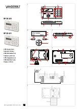
SPCK420
Brand: Vanderbilt Pages: 11

RP1016LCD
Brand: NAPCO Pages: 24

SLK-1
Brand: Russound Pages: 2

KP401-IE
Brand: Access Security Products Pages: 11

100
Brand: jablotron Pages: 8

HAA85WP
Brand: Velleman Pages: 37

MG32I
Brand: Magellan Pages: 2

Esprit+ 642
Brand: Paradox Pages: 34

WKP-100
Brand: Targus Pages: 9

KEYLESS 042
Brand: Manaras Opera Pages: 4

WCM-030
Brand: rako Pages: 4

FRM704
Brand: Uplift Desk Pages: 2

SD1-2HP2PS
Brand: MCDonald Pages: 4

Keypad EZ
Brand: BEST ACCESS SYSTEMS Pages: 2

PLK-MSP16
Brand: AMX Pages: 1

Novara SP-08-AX-EU
Brand: AMX Pages: 2

MIO DMS
Brand: AMX Pages: 1

Mio Modero Prestige
Brand: AMX Pages: 2


