

Quick Start Guide
MET-13E Metreau
®
13-Button Ethernet Keypad
Overview
This guide pertains to the MET-13E Metreau 13-Button Ethernet Keypad
(
FG5793-02
). The purpose of this document is to illustrate how the device is to
be installed and set up in its simplest configuration by a trained technician.
Environmental Requirements
The environmental requirements for the MET-13E are as follows:
•
Operating Temperature
: 32° F (0° C) to 104° F (40° C)
•
Storage Temperature
: 4° F (-15° C) to 140° F (60° C)
•
Operating Humidity
: 5% to 85% RH
Note:
Intended for indoor use only.
Dimensions
HWD: 4 11/16" x 6" x 1" (119mm x 152.5mm x 26mm)
Weight
Approximately 0.35 lbs. (0.16 kg)
Power
You can apply power to the MET-13E via any Power-over-Ethernet (PoE)
injector or switch which conforms to the 802.3af standard. Before installing and
mounting the Keypad, test to see that it can receive power.
Applying Power
Applying power to the MET-13E requires category cable and a PoE injector,
such as the PS-POE-AF-TC (
FG423-83
) available from AMX. The network
must be connected through the PoE injector to send power to the Keypad. The
category cable should only run through a common building. (A common building
is defined as: Where the walls of the structure(s) are physically connected and
the structure(s) share a single ground reference.)
1.
Connect the PoE injector to an AC outlet (~100-240V) using a standard
power cord.
2.
Connect the switch category cable to the Data In port on the PoE injector.
3.
Using a separate category cable, connect the Data & Power Out port on
the PoE injector to LAN Port on the Keypad.
Changing Buttons
The easiest way to remove and replace buttons on the keypad is to place the
keypad assembly face-down on a flat level surface, so that the buttons stay in
position until you are ready to remove them.
Important:
Disconnect the power supply and all wiring connections before
removing/replacing buttons on the keypad.
Important:
Before touching the device, discharge the static electricity from your
body by touching a grounded metal object.
1.
The faceplate is attached to the mounting plate via four plastic tabs (two on
each side of the faceplate). To remove the faceplate, gently pry it from
either side.
FIG. 1
Location of the plastic tabs on the MET-13E
2.
Gently lift each button off of their mounting posts on the circuit board.
3.
Select the location of the custom buttons and gently snap them into place
on the circuit board. Be sure to note the orientation of the LED window on
each button, to avoid accidentally mounting them upside down.
4.
Reattach the plastic faceplate.
Mounting Options
Mounts onto standard single gang US or EU back boxes.
• Each type of back box must adhere to its own specific safety approvals.
• Minimum internal clearance of (HWD) 2 5/8" x 1 3/4" x 1 5/8" (66.68mm x
44.45mm x 41.28mm)
Important:
Before touching the device, discharge the static electricity from your
body by touching a grounded metal object.
Wallbox Mounting
1.
Use the cutout dimension for the wallbox to cutout the install surface.
2.
Connect category cable to the LAN port on the rear of the keypad.
3.
Place the Mounting Plate on the wallbox; align the screw holes with
the mounting holes and fasten the Mounting Plate to the wallbox using
the supplied screws.
Note:
Do not overtighten the screws when mounting the Mounting Plate. The
device should be flush with mounting surface.
Daisy-Chaining Keypads
You can use the MET-13E as an individual keypad or in conjunction with the
MET-7X or MET-13X Metreau Ethernet Expansion Keypads. The Expansion
Keypads connect to the MET-13E via the 16-conductor ribbon cable included
with the expansion keypad.
Metreau keypads support daisy-chaining up to 3 keypads together.
Daisy-chained keypads receive power from a single Ethernet connection and
appear as a single NetLinx device.
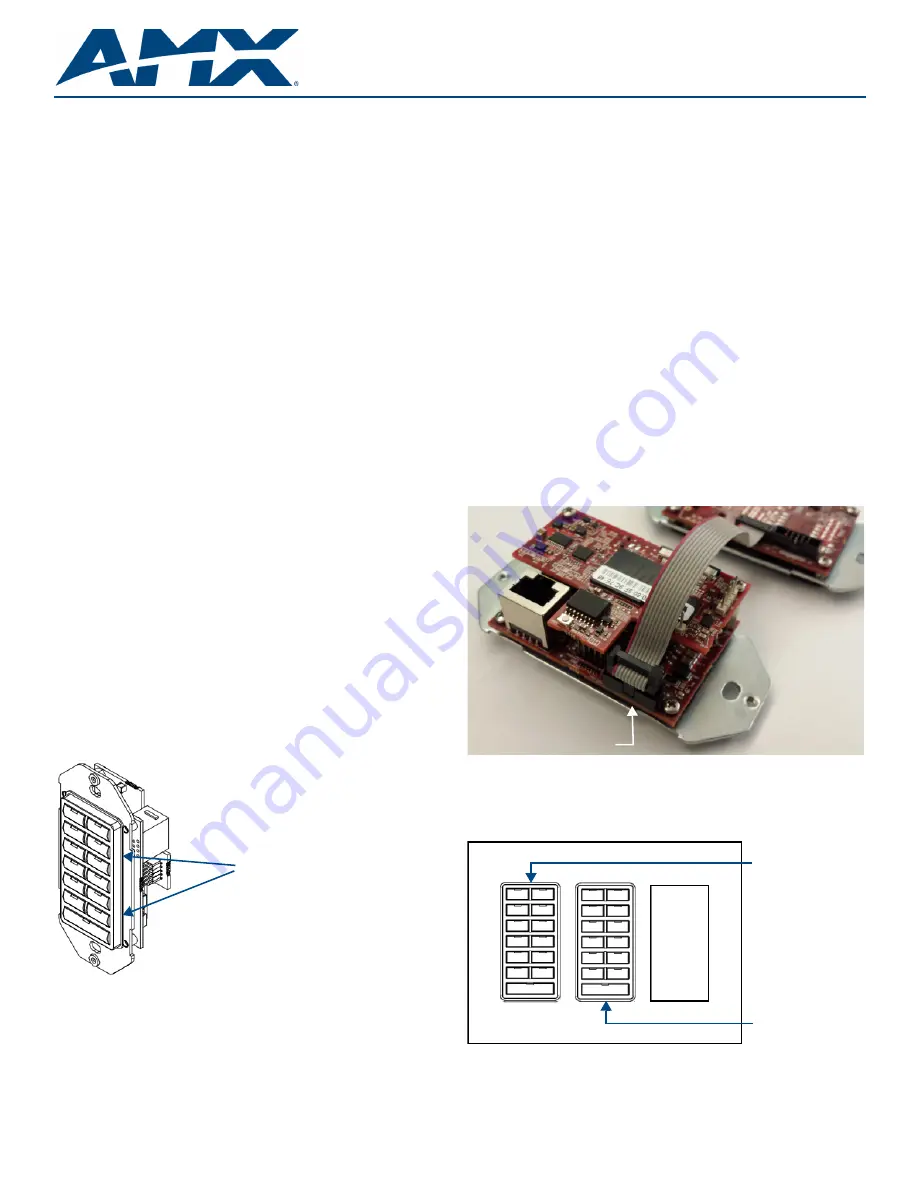
Use the 16-conductor ribbon included with the expansion keypad to connect to
the MET-13E (see FIG. 2).
FIG. 2
Daisy-chain connection between the MET-13E and an Ethernet Expansion
Keypad
Note:
If you are installing a single expansion keypad into a 3-gang back box,
install the expansion keypad in the space immediately adjacent to the primary
Ethernet keypad (see FIG. 3). Daisy-chaining is supported across a distance of
4” (101.6 mm).
FIG. 3
Install the keypads immediately adjacent to each other in a 3-gang back
box
Plastic tabs
Connect ribbon cable here
Primary keypad
Expansion keypad


